You are able to download printable version of this article in .pdf format for offline use!
Rotary Kilns
A prerequisite for the normal operation of a rotary kiln is the alignment of the rotation axis of its shell. Its curvatures even within the tolerance (2–3 mm) cause intensive wear of tires, support rollers and their bearings, increase the consumption of power to rotate the kiln, accelerate the destruction of the refractory lining and the metal shell.
Traditional means of inspecting the geometry of large-sized objects do not offer the required spatial accuracy and efficiency of measurements in real production conditions. Robotic industrial-geodetic systems are gaining wider application when performing high-precision measurements during the manufacture and operation.


Given the efficiency of measurements in production conditions, critical deviations from design geometric characteristics (alignment, perpendicularity, cylindricity, position, relative orientation, etc.) can be detected in real time and measures can be taken to minimize the harmful impact of abnormal geometry of an individual element on the performance of the entire process line.
Currently, most industrial-geodetic systems employ a positioning technology to inspect the geometry of large-sized complex objects. Using these systems, characteristic points (or a larger array of arbitrarily placed points) are located on the surface of an object. This data is used to calculate various geometric characteristics of the object: dimensions, center position, deviation from a given shape, object orientation in space and relative to
other subassemblies and mechanisms, dynamic changes in these characteristics (deformation, displacement).
Alignment of rotary kilns
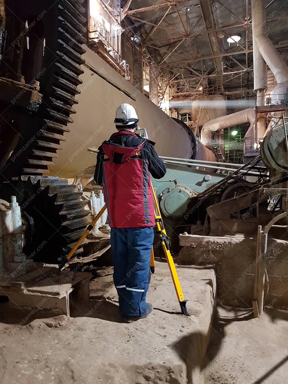
When aligning rotary kilns, an as-built survey is performed on the support rollers and tires on all supports, as well as a survey of the girth gear of the main drive. Using the developed method, our professionals calculate all the necessary data in a single coordinate system with reference to the horizontal plane. The data obtained make it possible to analyze all the geometric characteristics of a rotary kiln.
In case of zero visibility between the kiln tires, it may be required to set up an instrument in more than one location. In this case, a geodetic control network is created around the object (rotary kiln), fixing the coordinate system of the kiln. From each individual instrument station, at least four points of the geodetic network are observed.
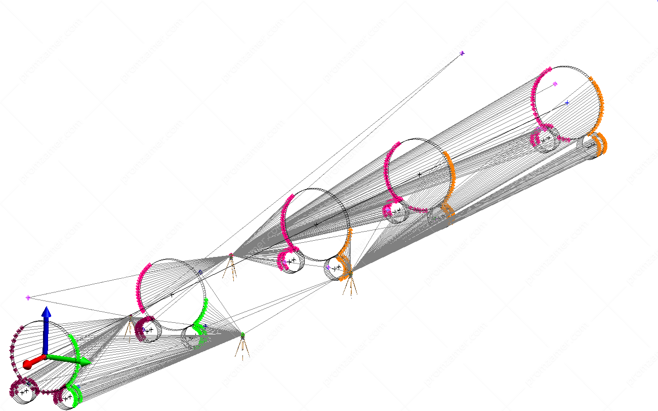
Общий вид полученных данных со всеми стоянками прибора.
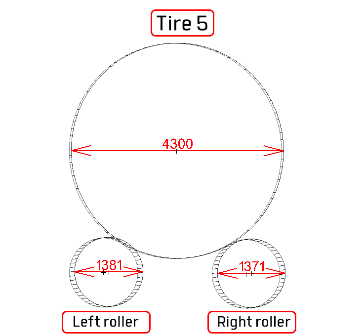
Actual mean diameters of support rollers and tires. End view.
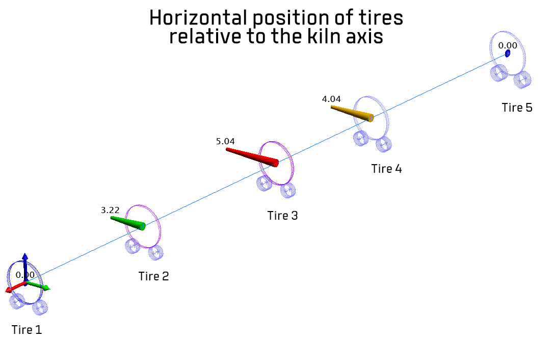
Position of tires in plan view relative to the kiln axis.
If we know the coordinates of all measured points in a single coordinate system of a rotary kiln, we can determine:
- actual diameters of the tires and support rollers of the rotary kiln;
- spatial position of tires relative to the axis of the rotary kiln;
- central angles and geometry of the spatial position of rotation axes of support rollers and tires on all
- supports of a rotary kiln;
- turns and slopes of support rollers of a rotary kiln.
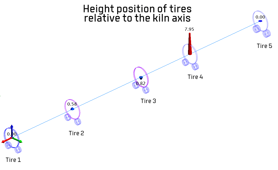
Height position of tires relative to the kiln axis.
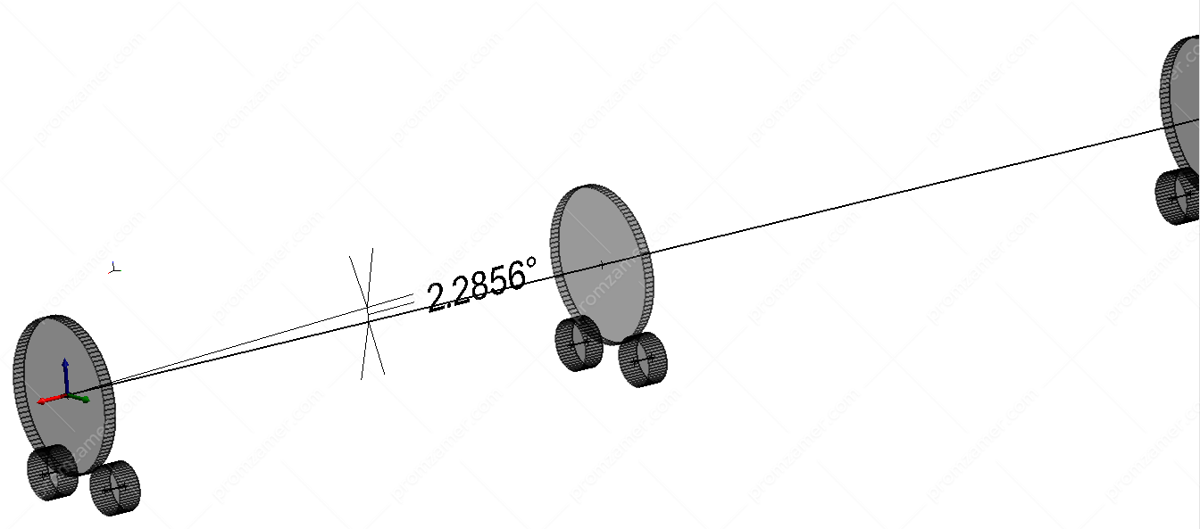
Фактический угол наклона оси печи относительно горизонта.
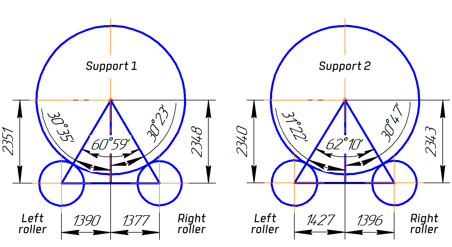
Determination of the geometry of support rollers and tires. End view.
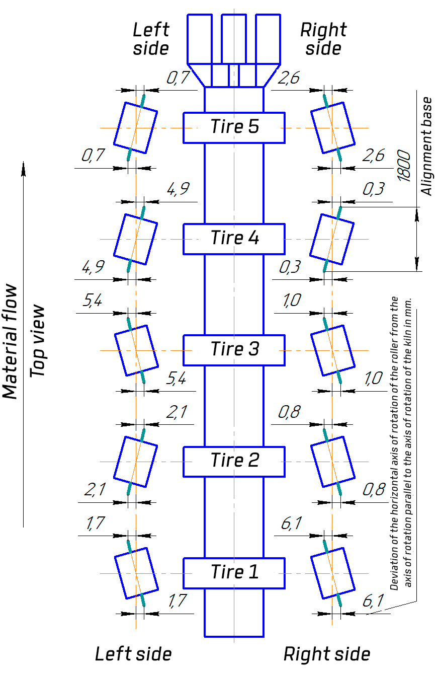
Turns of kiln support rollers in horizontal plane (in plan view).
Tell us about your project
We will contact you in 1 working day and prepare the info you need.
