You are able to download printable version of this article in .pdf format for offline use!
Reconciliation of ore grinding mills
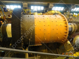
About ore grinding mills
Reliable and efficient operation of ore grinding mills is largely dependent on compliance with the accuracy requirements of the design documentation. With the dimensions of main equipment of up to 10–30 m, it is required to ensure the design geometry with an accuracy of 0.05–0.2 mm.
Given the significant dimensions and weight of the main equipment of mining and processing complexes, the fit-up of the entire process line is often not performed, and sometimes impossible. Therefore, it is necessary to monitor compliance with the design geometry of parts and assemblies throughout the entire cycle of creating and operating this equipment – at the manufacturer’s factory, during installation, operation, and scheduled maintenance.
Traditional means of inspecting the geometry of large-sized mechanical engineering objects do not offer the required spatial accuracy and efficiency of measurements in real production conditions. Robotic industrial-geodetic systems are gaining wider application when performing precise measurements during the manufacture and operation of unique facilities in Russia and abroad.
They are used in the most efficient way for measuring large-sized (more than 2 meters) objects with an accuracy of up to one and two decimal places of a millimeter.
Given the efficiency of measurements in real production conditions, critical deviations from design geometric
characteristics (alignment, perpendicularity, cylindricity, position, relative orientation, etc.) can be detected in real time and measures can be taken to minimize the harmful impact of abnormal geometry of an individual element on the performance of the entire process line.
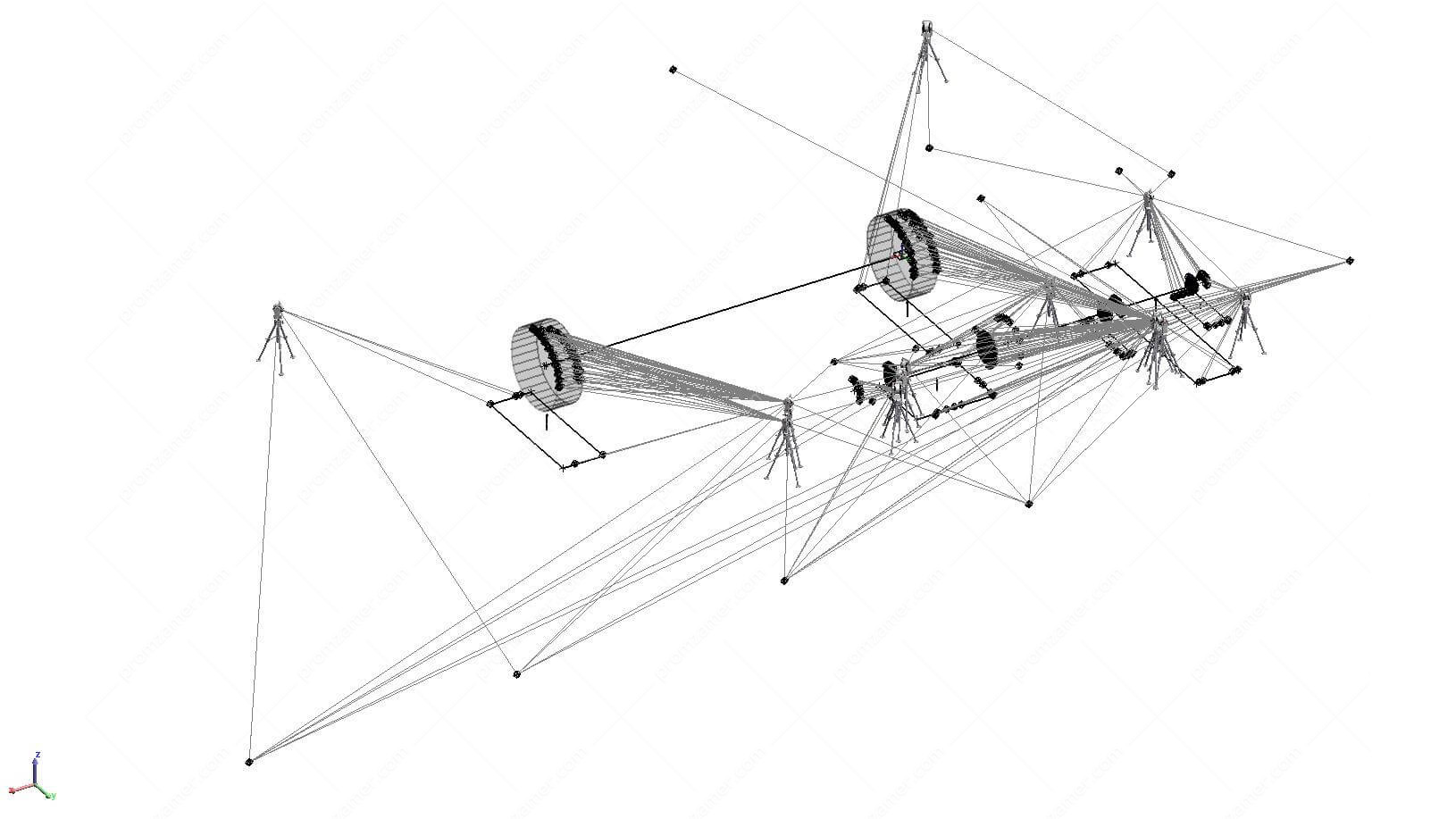
Currently, most industrial-geodetic systems employ a positioning technology to inspect the geometry of large-sized complex objects. In this case, the spatial coordinates of the characteristic points are determined on the surface of the parts of the process line under examination, and the analysis of their relative positions is used to calculate the required geometry.

Slope of axis of the mill and drive.
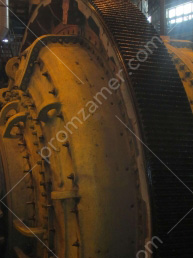
Checking the trunnion profile.
Общий вид полученных данных.
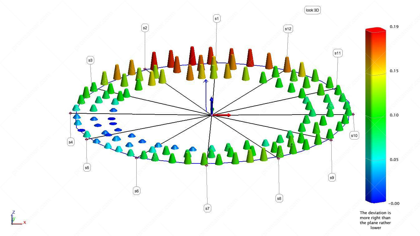
Неплоскостность.
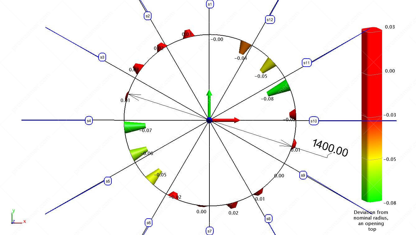
Форма цапфы.

Направление уклона и величина уклона.
Our professionals have performed a package of works to determine the geometry of steelwork beams of flotation machines 1–6.
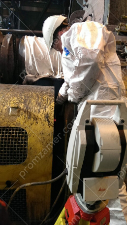
The vertical position of the axis of a flotation machine drive directly affects the service life of the machine’s elements. Also, slight deviations of geometry from design values may exert increased loads on bearings, thereby reducing their service life by several times. Flotation machines are mounted on the support beams, therefore, the vertical position of the drive axis determines the horizontal position of the support beams. To avoid disassembling the drive housings, it was decided to determine the horizontal position of the support beams. All work was performed using a Leica AT402 laser tracker. This allowed for horizon reference with an accuracy of ±1 arc-second and guaranteed the accuracy of measurements in the entire volume ±0.1 mm.
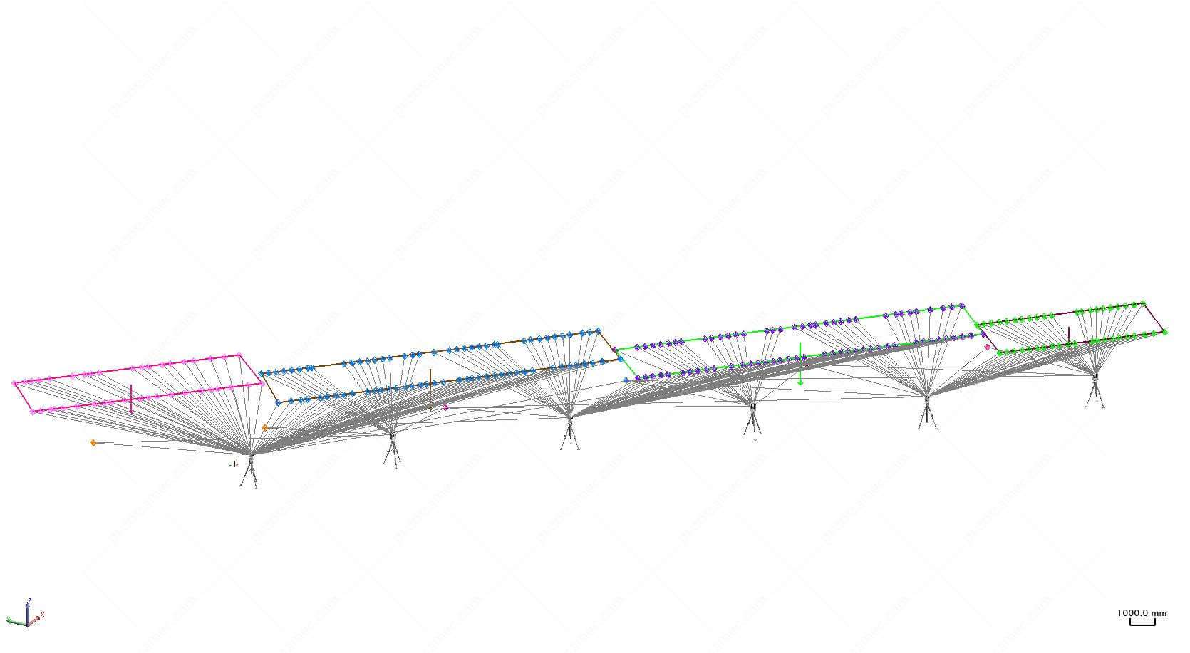
Общий вид полученных данных.
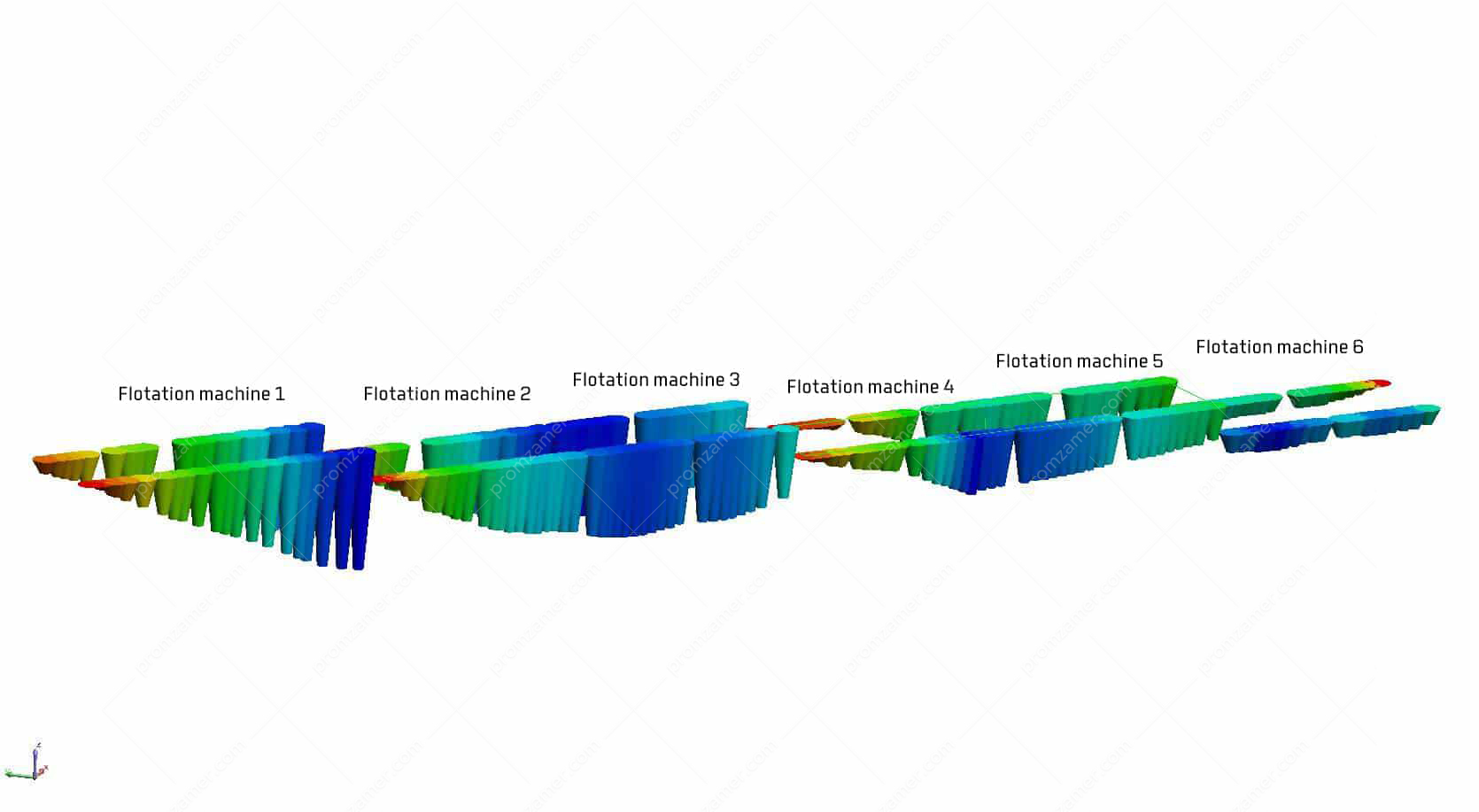
General view of the deviation of the beams from the horizontal plane.
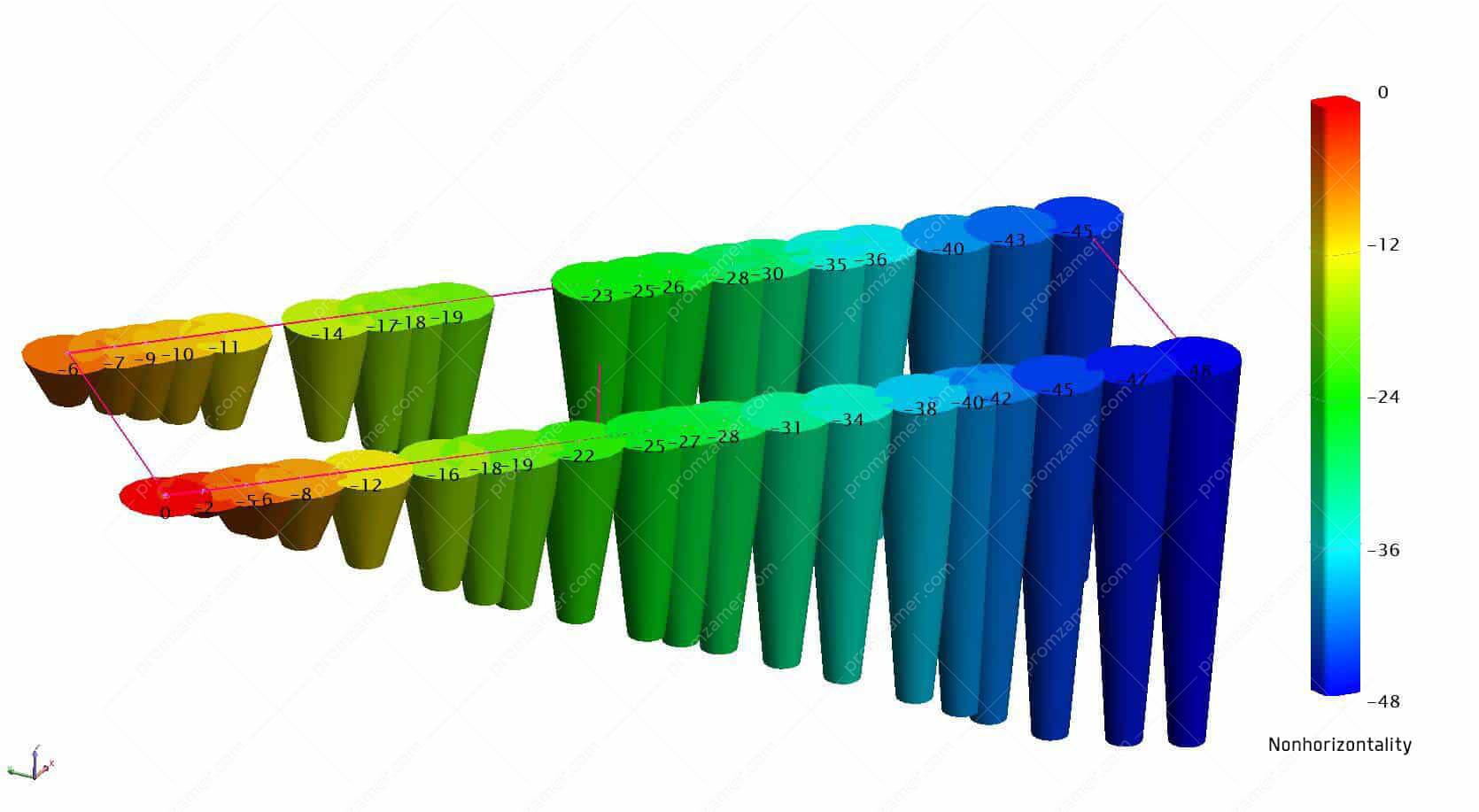
Slope of the support beams of flotation machine 1 in measuring points.

Average direction and grade of slope.
After receiving the result, the customer can see problem areas and can take measures to eliminate the problem itself, and not its symptoms, such as replacing bearings, etc.
Using the data obtained, it is possible to calculate shim plates, and if necessary, to align the equipment according to the instrument when installers can see deviations of the elements being adjusted from design values in real time, which guarantees high quality of the adjustment.
Alignment of ore grinding mills

Общий вид мельницы.
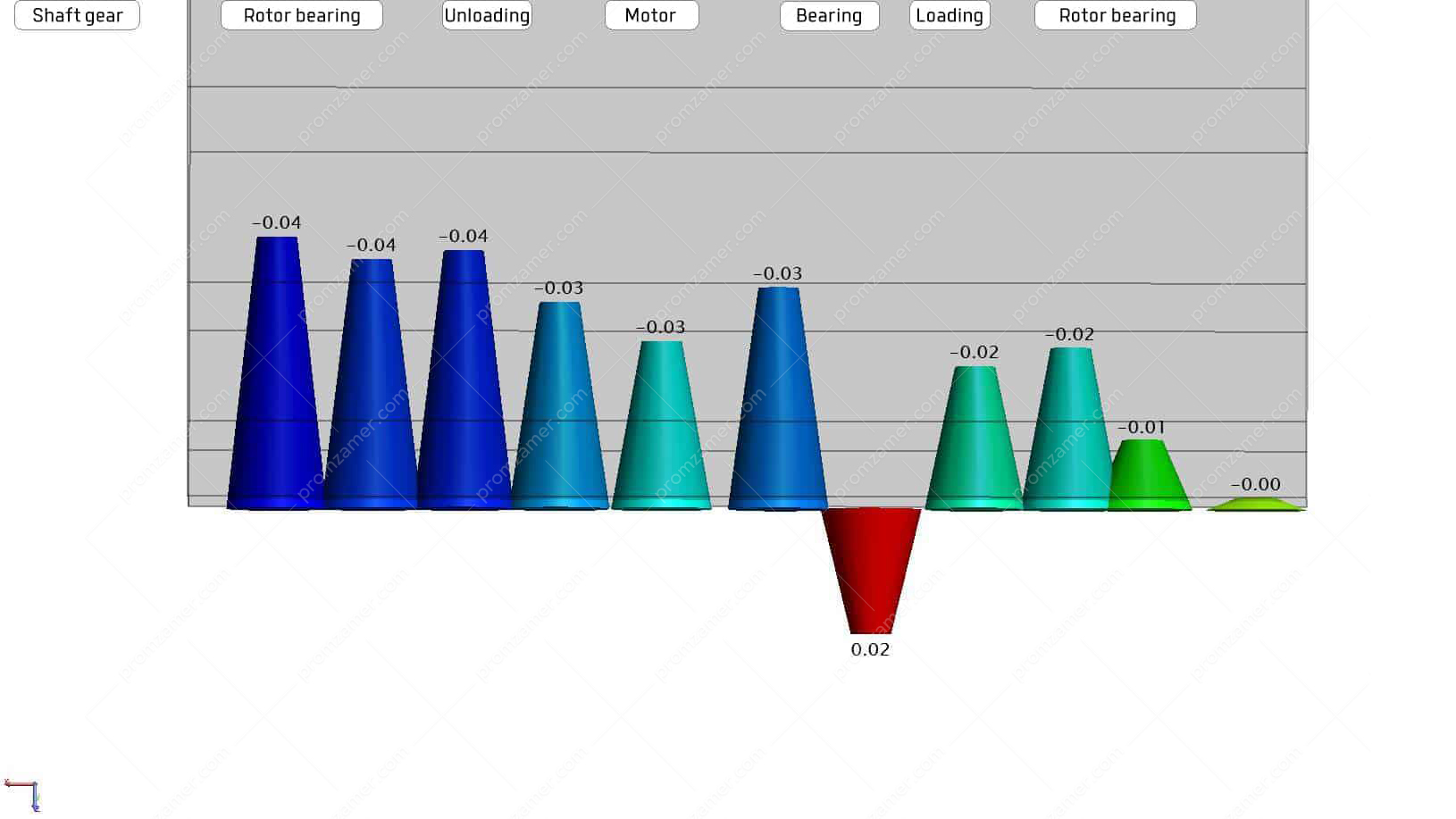
During the alignment of ore grinding mills, the bed frames of the mill’s support bearings are measured and the spatial position of its axis is determined. Also, the support beams, motor–shaft gear lines, and bearing seats are measured, and the axis of the motor and the shaft gear are determined. Using the developed method, we obtain all data in a single coordinate system with reference to the horizontal plane and, if necessary, to the local geodetic network. The data obtained make it possible to analyze all the geometric characteristics of a mill and its drive (drives). They also allow us to pre-calculate the shim plates necessary to achieve the parameters according to design values.
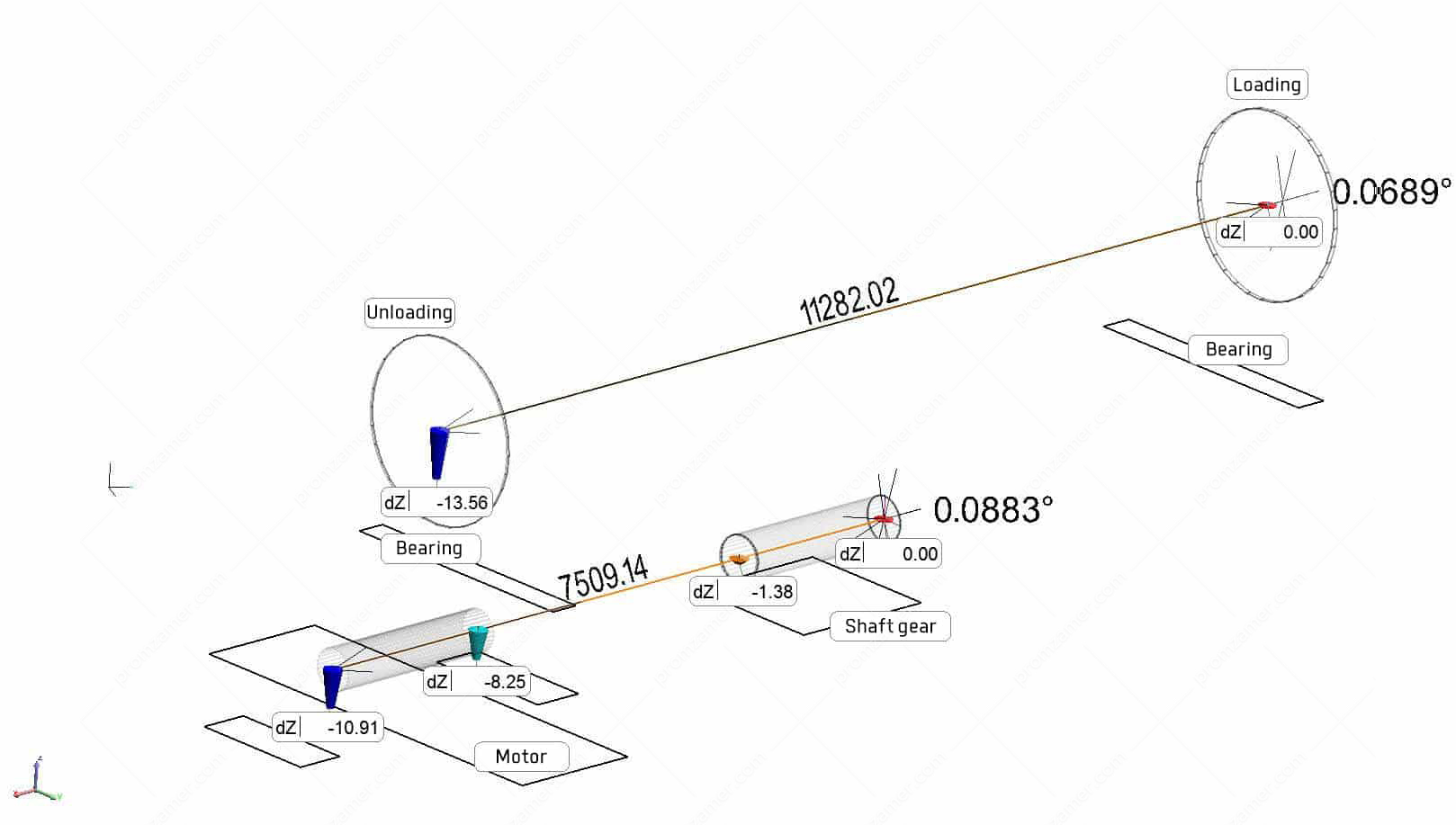
Unacceptable deviation of the mill and drive axes from the horizon.
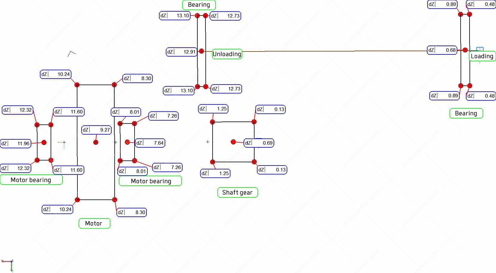
We performed a preliminary calculation of shim plates to align the mill and drive axes.
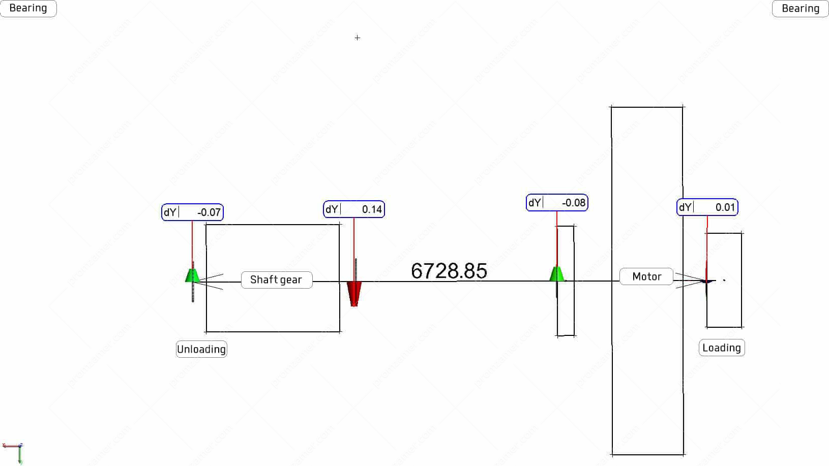
Turn and tilt of the drive axis relative to the mill axis in the horizontal plane. Adjustment was performed using a laser tracker during scheduled maintenance.
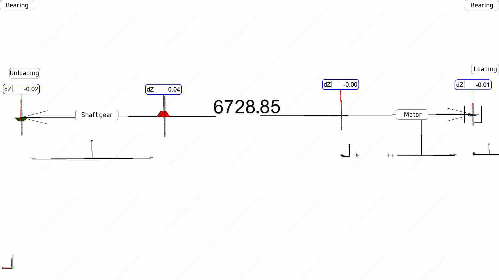
Turn and tilt of the drive axis relative to the mill axis in the vertical plane. Adjustment was performed using a laser tracker during scheduled maintenance.
At the stage of installing the mill, using a laser tracker, we can align all embedded frames with an accuracy of up to ±0.02 mm and ensure that the drive and mill axes are parallel in space. During scheduled maintenance, alignment of the mill and its drive using a laser tracker not only speeds up the process, but also guarantees the quality of work done.
Proper adjustment results in decreased heating of bearings, extension of their service life, and uniform wear of the lining. In turn, it reduces unscheduled downtime of mills, which saves maintenance costs incurred by the customer.
3D laser scanning
3D laser scanning is a technology that allows you to contactlessly determine the spatial coordinates of a large number of points on the surface of the measured object, the so-called point cloud. Typically, an instrument uses the polar principle to determine the points: angle sensors measure horizontal and vertical angles, a phase laser range finder measures distances.
When scanning complex objects, surveying from one instrument station is not enough as only a part of the surfaces of the object being measured falls into the scanner’s working range, so several stations have to be used. Scans from different instrument stations are then consolidated into a single coordinate system using special benchmarks.
Laser scanning technology may be in demand:
- to determine the magnitude of the deformation of steel or concrete structures;
- during construction, to identify design deviations;
- to build models and draw up dimensional drawings of an object in preparation for upgrade;
- to observe the deformation of an object under various influences;
- during virtual assembly of a large-sized object;
- for overall inspection (of mines and transport tunnels);
- to determine the capacity of complex tanks.
A point model allows you to build various sections of objects to analyze the geometry, create drawings, or compare with a nominal CAD model. To detect deformation, you can compare scans of the same object made at different times.
This technology also allows you to move scanned large-sized objects through scanned transport and process openings and tunnels, with clearance control at each stage.
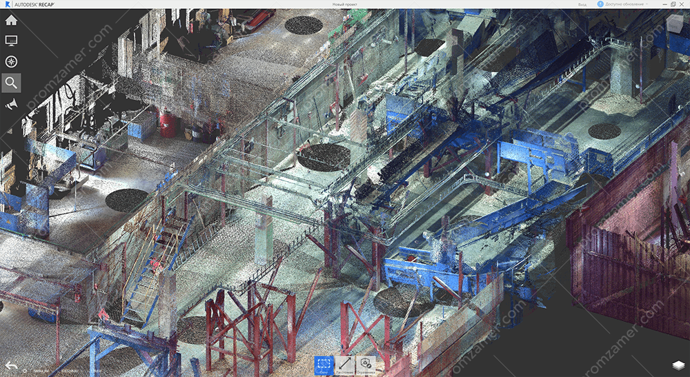
Сканирование цеха.
Показана точечная модель.
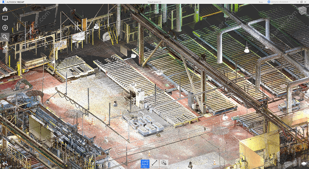
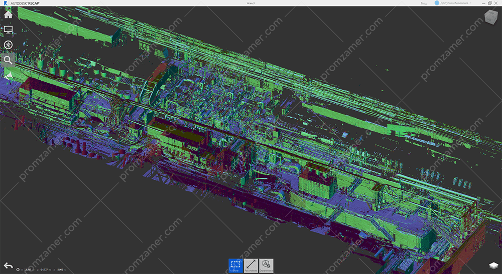
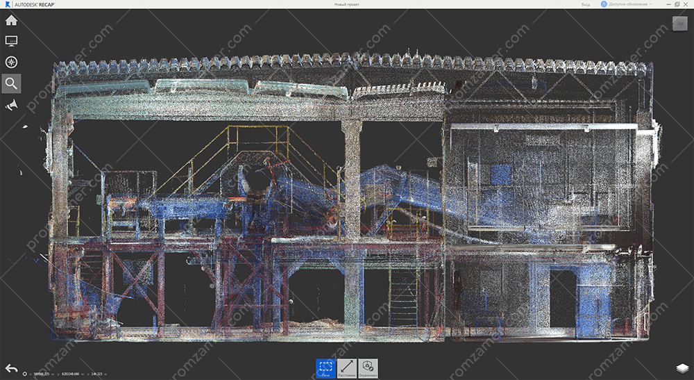
Точечная модель всего корпуса.
Tell us about your project
We will contact you in 1 working day and prepare the info you need.
