You are able to download printable version of this article in .pdf format for offline use!
Alignment of Paper and Cardboard Machines
About high-accuracy alignment of the basic elements of paper machines
High-accuracy alignment of the basic elements of paper machines, cardboard machines, corrugators is an integral part of the process when installing new equipment, upgrading equipment already installed or during scheduled maintenance. With the dimensions of main equipment of several dozens, and sometimes hundreds of meters, it is required to ensure the design geometry with an accuracy of 0.05–0.3 mm.
Deviation of the geometry of a machine’s main working parts directly affects the product quality.
Traditional means of inspecting the geometry of large-sized objects do not offer the required spatial accuracy and efficiency of measurements in real production conditions. Robotic industrial-geodetic systems are gaining wider application when performing high-precision measurements during the manufacture and operation.
Given the efficiency of measurements in production conditions, critical deviations from design geometric characteristics (alignment, perpendicularity, cylindricity, position, relative orientation, etc.) can be detected in real time and measures can be taken to minimize the harmful impact of abnormal geometry of an individual element on the performance of the entire process line.
Currently, most industrial-geodetic systems employ a positioning technology to inspect the geometry of large-sized complex objects. In this case, the spatial coordinates of the characteristic points are determined on the surface of the parts of the process line under examination, and the analysis of their relative positions is used to calculate the required geometry.
Installation, adjustment of sole plates and embedded parts
Sole plates are the basic elements for installing the main equipment of paper and cardboard machines, therefore, they, as the initial link, are subject to the highest precision requirements. It is necessary to ensure the leveling and flatness of the installation of plates and/or embedded parts of maximum 0.05 mm.
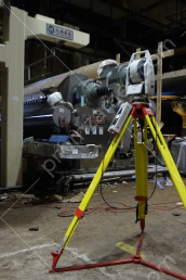
To ensure such accuracy, our professionals use only the best high-precision instruments in this class – laser trackers produced by Leica (Switzerland). These instruments allow us to guarantee the accuracy of the installation of plates and other equipment, if required, up to 0.05 mm in the measuring volume.

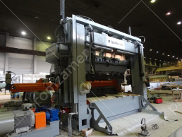
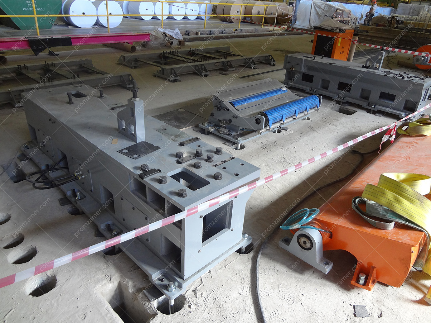
Монтаж и регулировка закладных под установку пресса 1-2 группы.
Установлено оборудование пресса 1-2 группы.
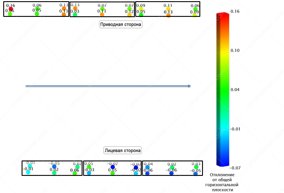
Исполнительная съемка по закладным. Приводная сторона по просьбе заказчика выставлена выше относительно лицевой.

Режим регулировки любых элементов в пространстве на экран выводятся отклонения от номинального положения.
In addition, hardware and software capabilities and methods developed by our professionals allow us to see deviations in real time and perform all adjustment and tightening, as necessary, to achieve the required value. This approach to adjustment allows us to reduce the number of iterations as well as increase the speed and accuracy of installation and adjustment work.
Inspection and alignment of the main parts of paper machines, cardboard machines and corrugators
Adjusting the position of the boxes of paper and cardboard machines with dewatering elements when using laser trackers takes no more than one working shift. In this case, both the distance from the lip as per the installation diagram and the height position are adjusted.
This technology allows us to make adjustments without removing the wire from the wire table, which significantly saves time for this stage of adjustment work.

Выверка гофроагрегата.

Отклонения высотного положения плит сушильного стола от горизонтальной плоскости, расположенной на высоте -505 мм в принятой системе координат.
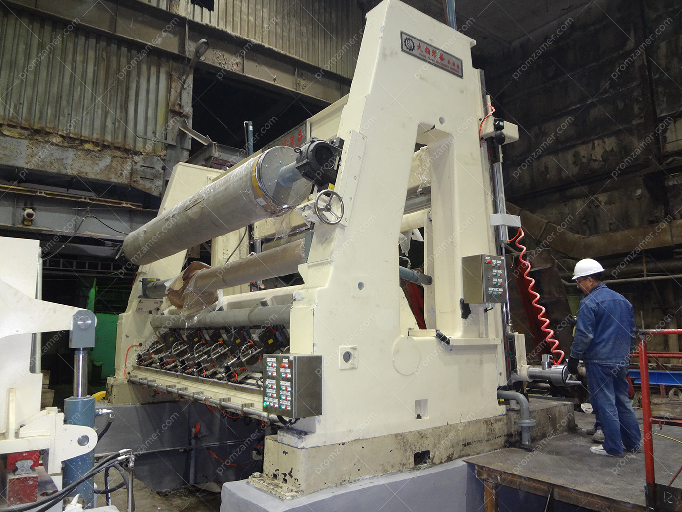
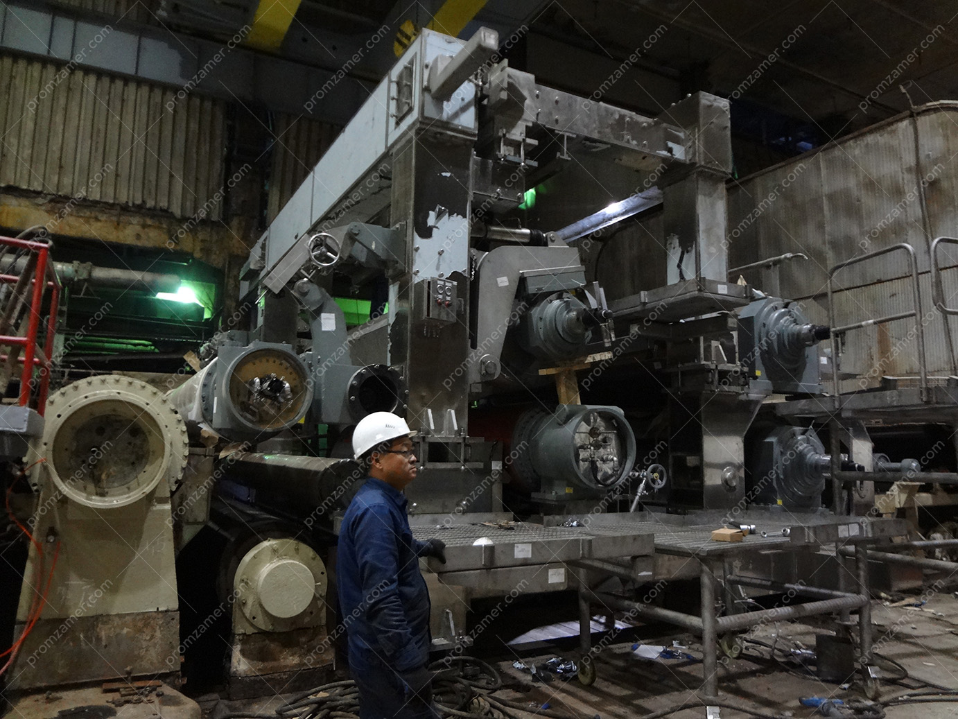
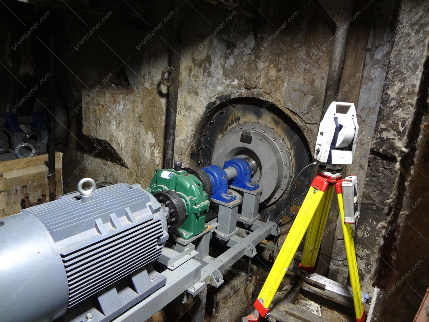
Сопровождение монтажа и регулировка валов ПРС.
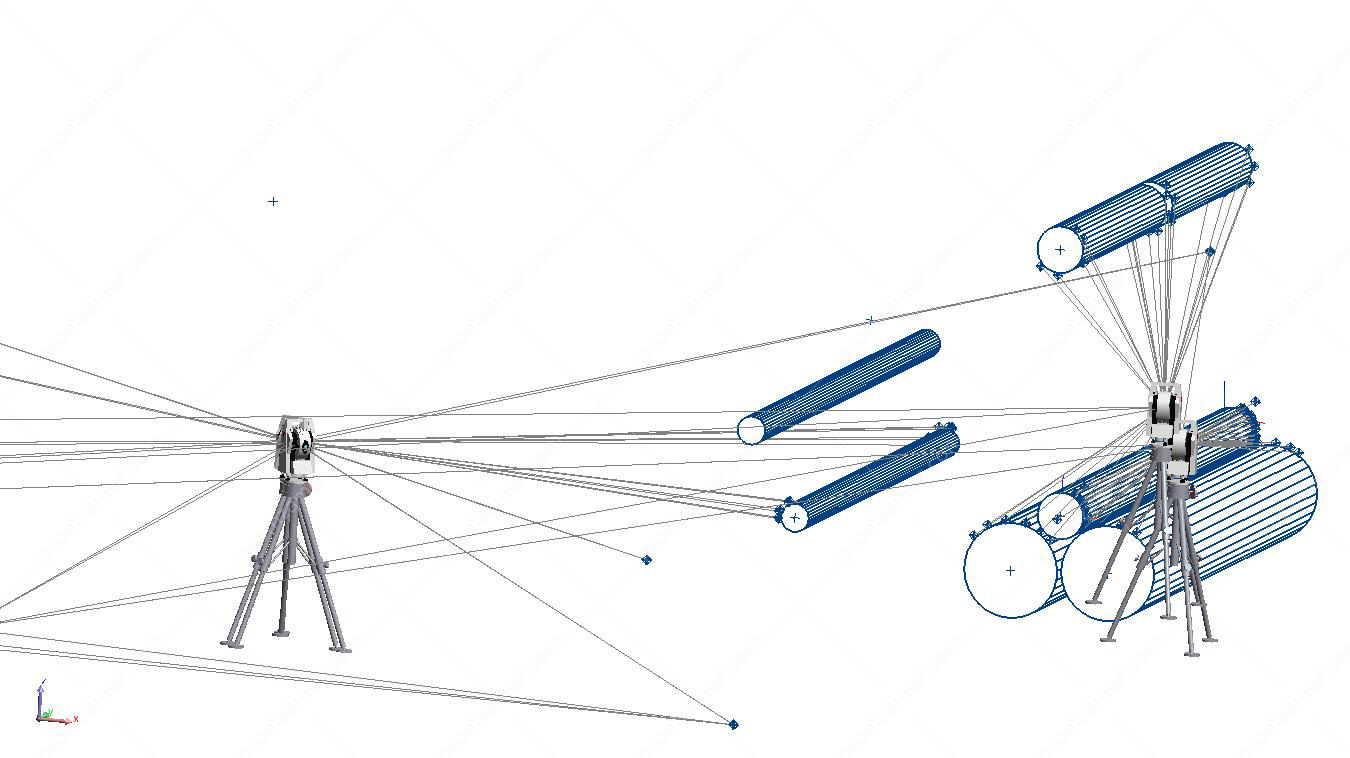
Общий вид полученных данных при измерении и регулировке валов ПРС.
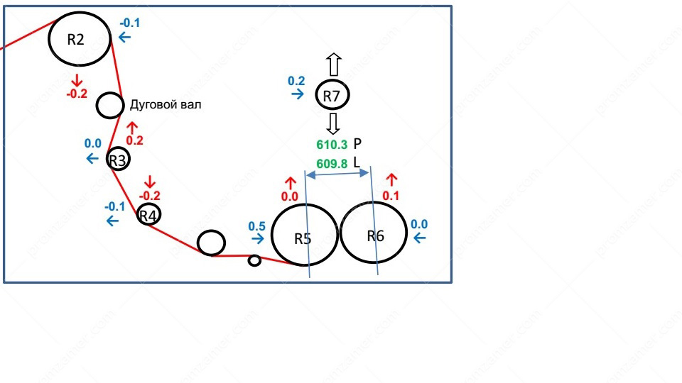
Результат после регулировки валов ПРС КДМ.
Alignment of a rewinder is in demand during installation and operation. During installation, our professionals apply markings for drilling holes for embedded frames or anchors. It is followed by fine adjustment to the design position. Adjustment of rewinder rolls is also an integral part of the proper operation of a machine and requires skilled professionals as there are more geometric parameters to align than with the rolls of drying and press sections.
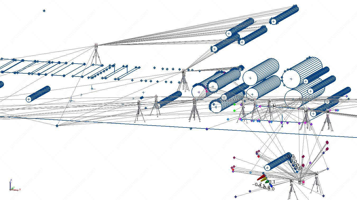
Выверка валов прессовой группы общий вид полученных данных.

Positioning of rolls after alignment.
Thanks to our background and best practices in high-precision measurements, we are able to perform all alignment activities in a single coordinate system, even if rolls are located at different levels. We submit the form to the customer immediately after the survey is completed. All information received is processed automatically during the survey, which reduces the survey-to-decision time.
Alignment of other pulp and paper equipment
Modernization of the pulp and paper industry introduces new links of the process chain that are integrated with existing ones. Below is an example of the adjustment of a pulper’s bed frame. The task was to ensure the perpendicularity of the shaft to the flange in all planes and pour the frame with concrete mixture in this position.
Регулировка положения фундаментной рамы гидросбивателя.
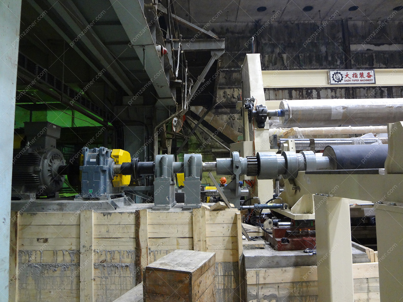
Установка рам основания ПРС.
When installing new equipment, there is a need to mount several overall frames that are not interconnected and ensure design horizontal and vertical orientation in space for further installation of a common element on them, with high accuracy.
During the installation of the unwinder section drive, we checked the quality of the pre-installation, identified unacceptable deviations of the drive line in the horizontal plane, which can be eliminated only by adjusting the bed frame, and it was corrected before pouring the frame with concrete mixture.
Выверка соединений привода и вала.
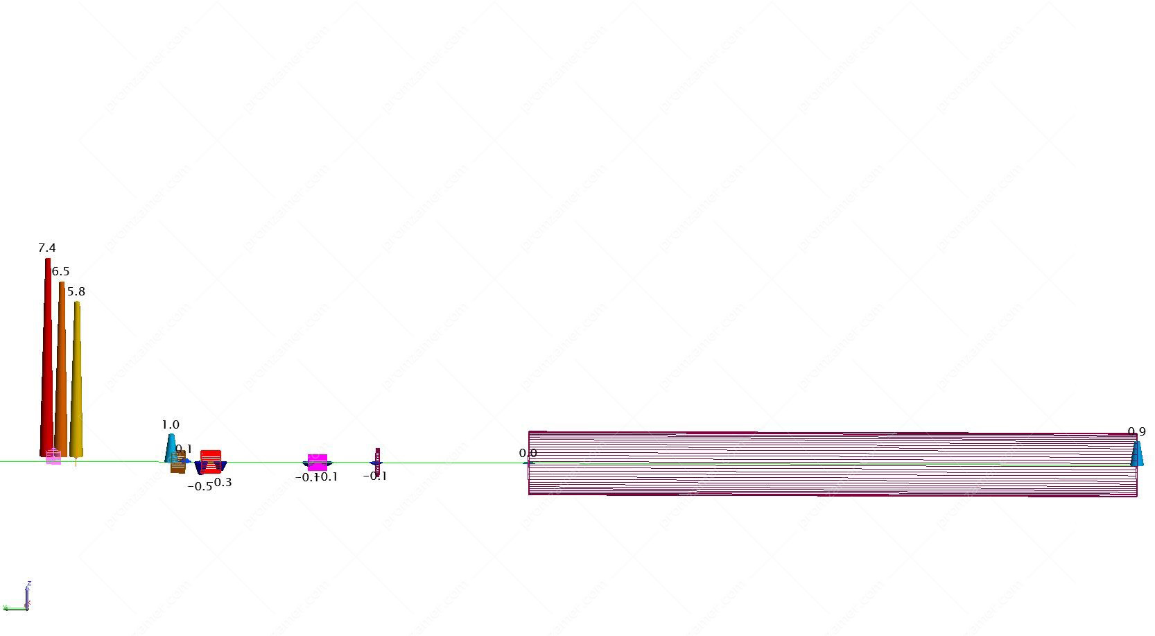
Недопустимые отклонения линии привода в горизонтальной плоскости.
Tell us about your project
We will contact you in 1 working day and prepare the info you need.
