You are able to download printable version of this article in .pdf format for offline use!
Hydropower Sector
Reliable and efficient operation of hydraulic structures
Reliable and efficient operation of hydraulic structures is largely dependent on compliance with the accuracy requirements of the design documentation. With the dimensions of main equipment of up to 10–20 m, it is required to ensure the design geometry with an accuracy of 0.02–0.05 mm.
Given the significant dimensions and weight of the main equipment of hydraulic facilities, the fit-up of the entire process line is often not performed, and sometimes impossible. Therefore, it is necessary to monitor compliance with the design geometry of parts and assemblies throughout the entire cycle of creating and operating this equipment – at the manufacturer’s factory, during installation, operation, and scheduled maintenance.

Traditional means of inspecting the geometry of large-sized mechanical engineering objects do not offer the required spatial accuracy and efficiency of measurements in real production conditions. Robotic industrial-geodetic systems are gaining wider application when performing precise measurements during the manufacture and operation of unique facilities in Russia and abroad.
They are used in the most efficient way for measuring large-sized (more than 2 meters) objects with an accuracy of up to one and two decimal places of a millimeter.
Given the efficiency of measurements in real production conditions, critical deviations from design geometric
characteristics (alignment, perpendicularity, cylindricity, position, relative orientation, etc.) can be detected in real time and measures can be taken to minimize the harmful impact of abnormal geometry of an individual element on the performance of the entire process line.
Currently, most industrial-geodetic systems employ a positioning technology to inspect the geometry of large-sized complex objects. In this case, the spatial coordinates of the characteristic points are determined on the surface of the parts of the process line under examination, and the analysis of their relative positions is used to calculate the required geometry.
Our professionals develop and implement new technologies for aligning the main equipment of hydraulic structures that ensure the required accuracy and high efficiency. The proposed solutions are based on the latest developments in the fields of applied geodesy, information and computer technologies. Mobile industrial-geodetic positioning systems allow for measuring such large-sized structures as gates of water sluices and navigation passes, rotors and stators of hydraulic units, runners of hydraulic turbines, the shape of labyrinth seals, working shaft, extension shaft, guide vanes, etc., with an accuracy of up to two decimal places of a millimeter in real production conditions.
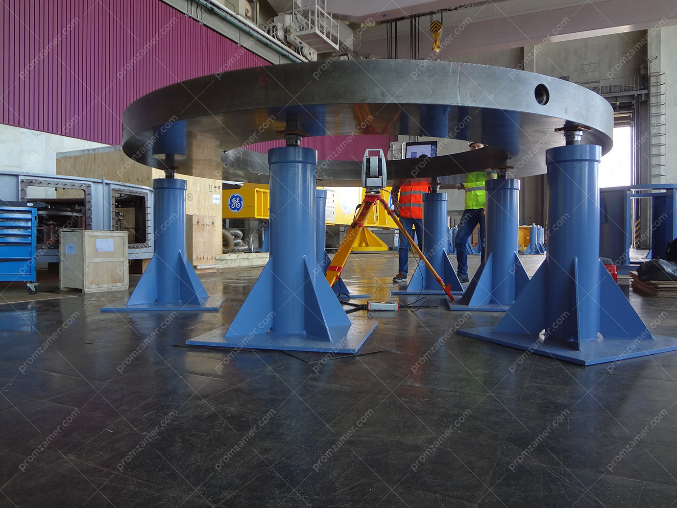
Диск подпятника. Выставление на опорах в одну плоскость.
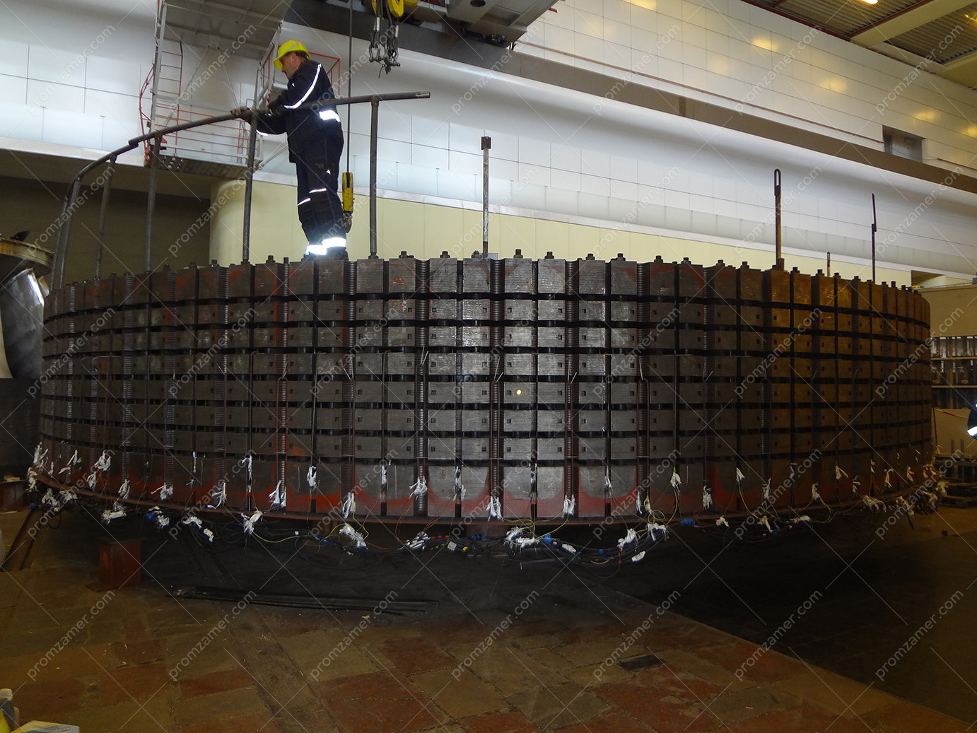
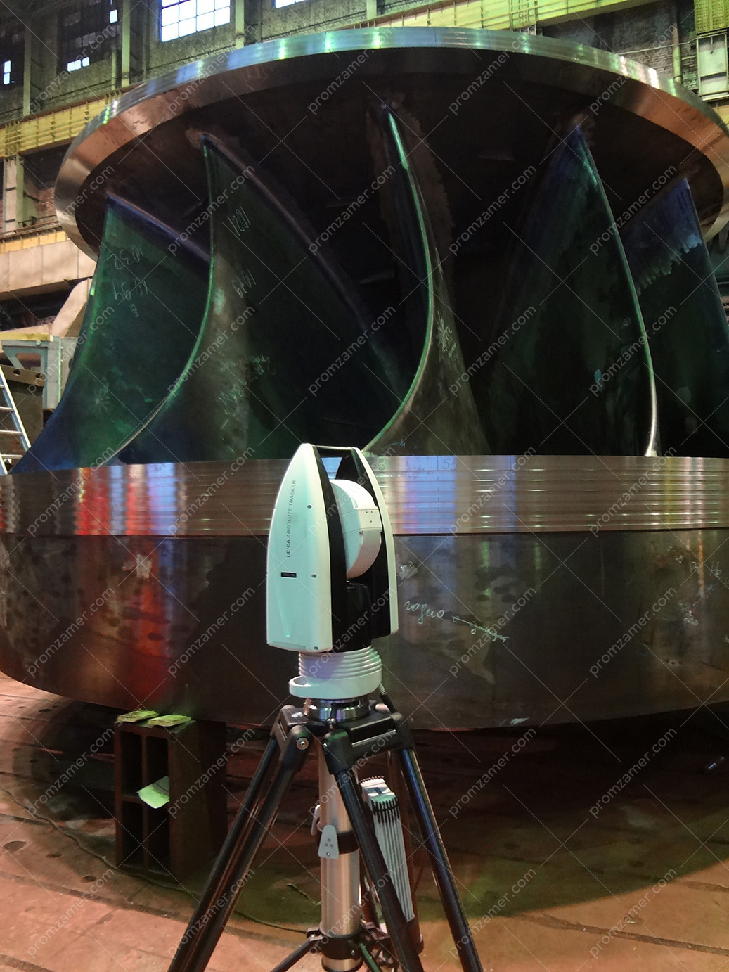
Обод ротора на монтажной площадке.
Отклонение верхней плоскости диска относительно нижней.
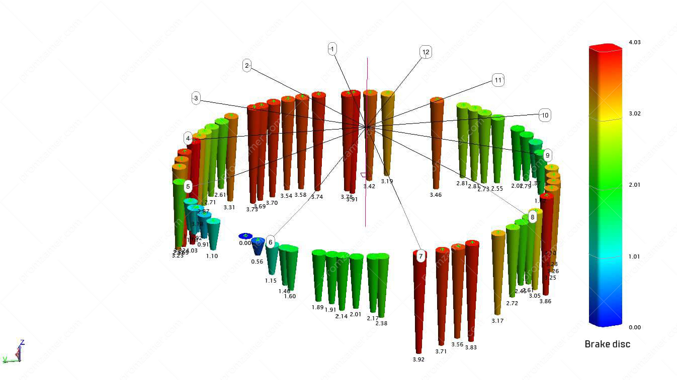
Brake disc shape.

Rotor rim shape. Section top.
Geometry inspection of shafting elements of a hydraulic unit
Measurements using a positioning technology can be performed for any orientation of the measured object relative to the horizon. The illustrations show the process of determining the misalignment of the base shaft collars and the orientation of the flanges relative to the shaft axis. Measurements were performed at the installation site. The data obtained allow for determining not only the axis misalignment and non-perpendicularity, but also its direction. This information allows for minimizing the impact of the non-perpendicularity of the shaft axis flange on the overall coaxial alignment by rational placement of a mating part of the process chain. For a hydraulic turbine shaft, a rotor bushing and a runner may become such a part.
The measurement data allowed us to perform a virtual assembly of the shaft line. Moreover, it was possible to calculate the rational rotation of the runner, which would partially compensate for the non-perpendicularity of the upper flange of the hydraulic turbine shaft.
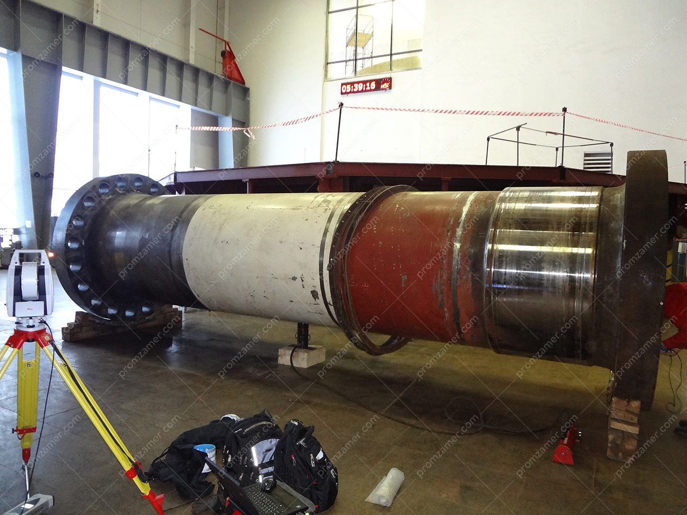
Вал. Общий вид.
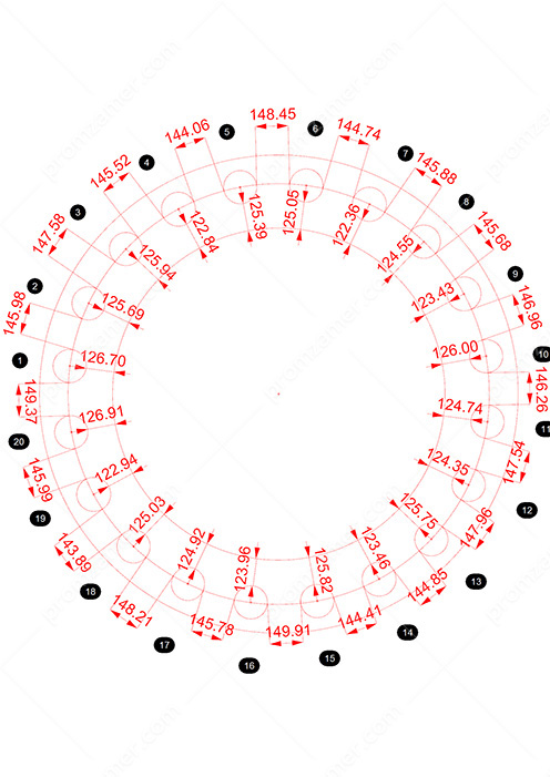
Размеры расположения крепежных отверстий нижнего фланца вала согласно схеме заказчика.
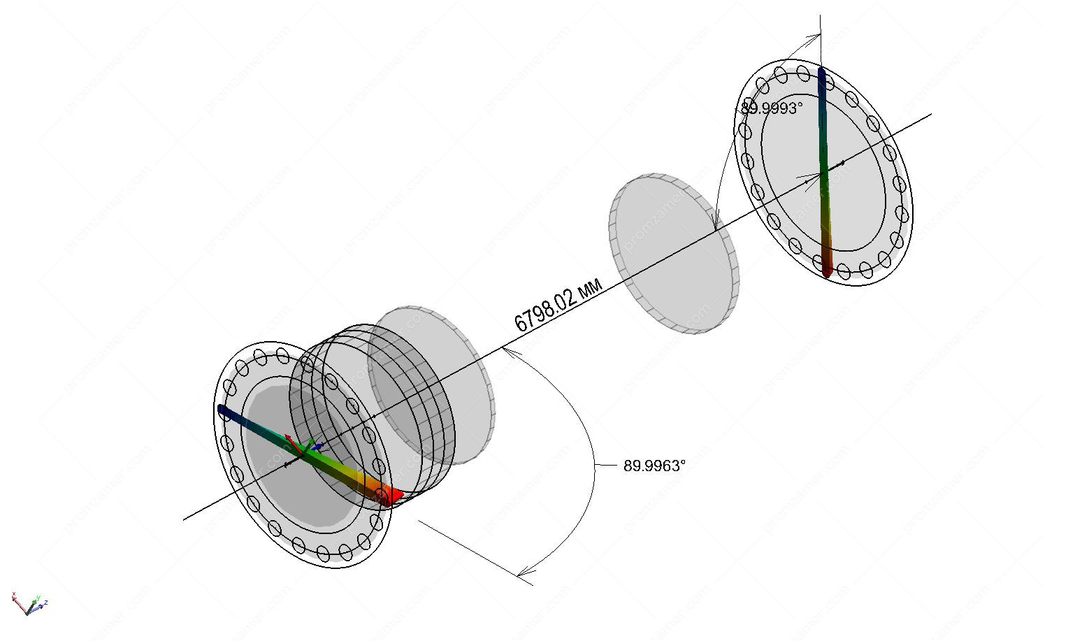
Вал. Неперпендикулярность фланцев к оси вала.
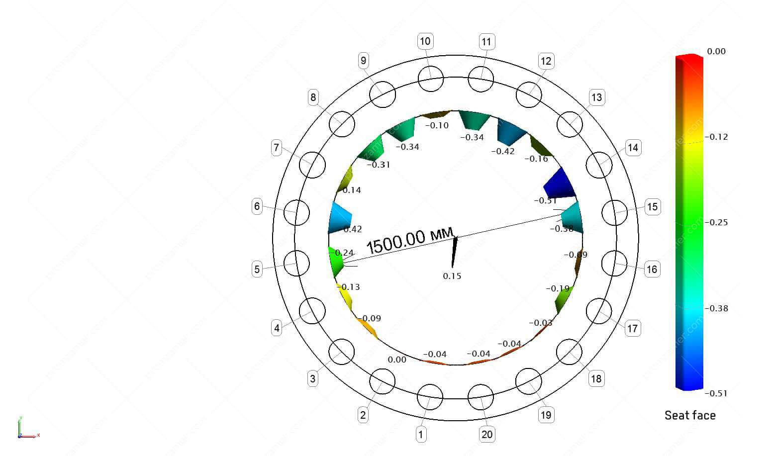
Displacement of the seat face relative to the shaft axis.
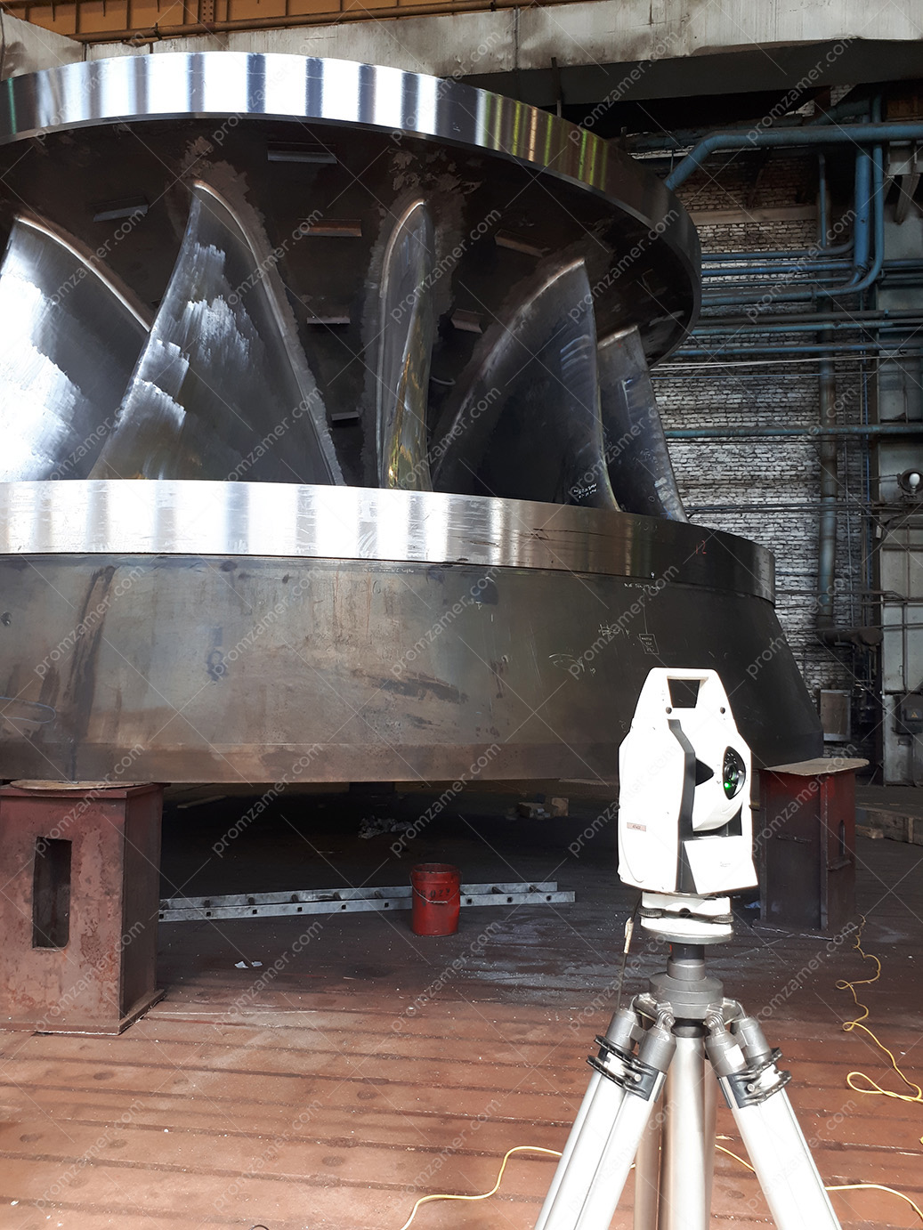
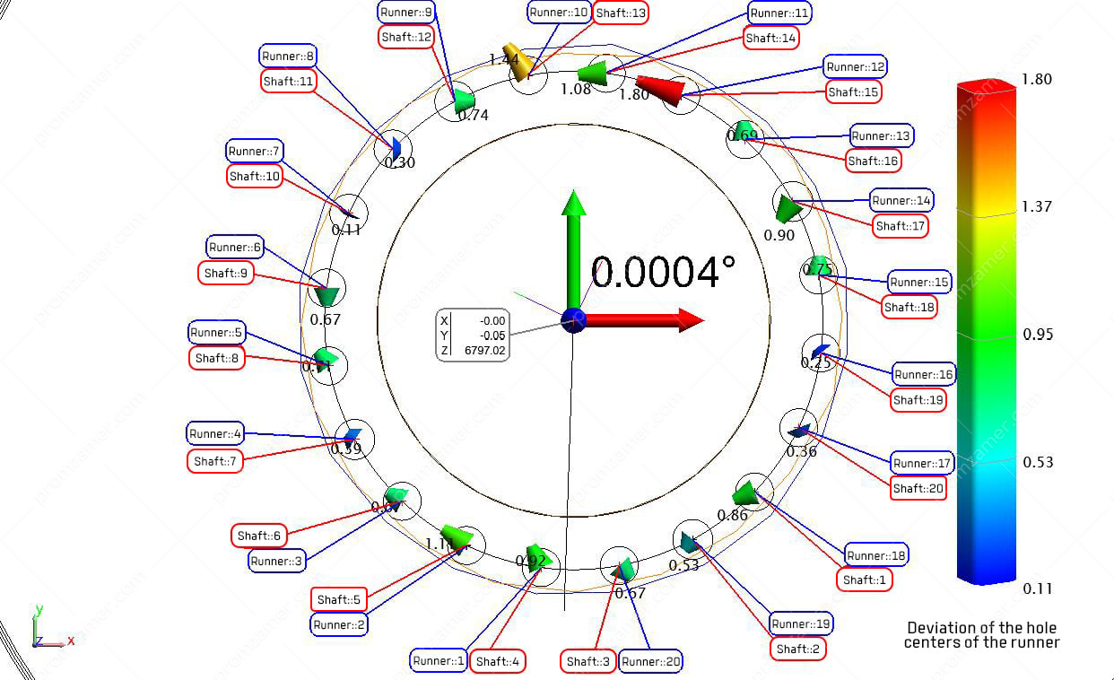
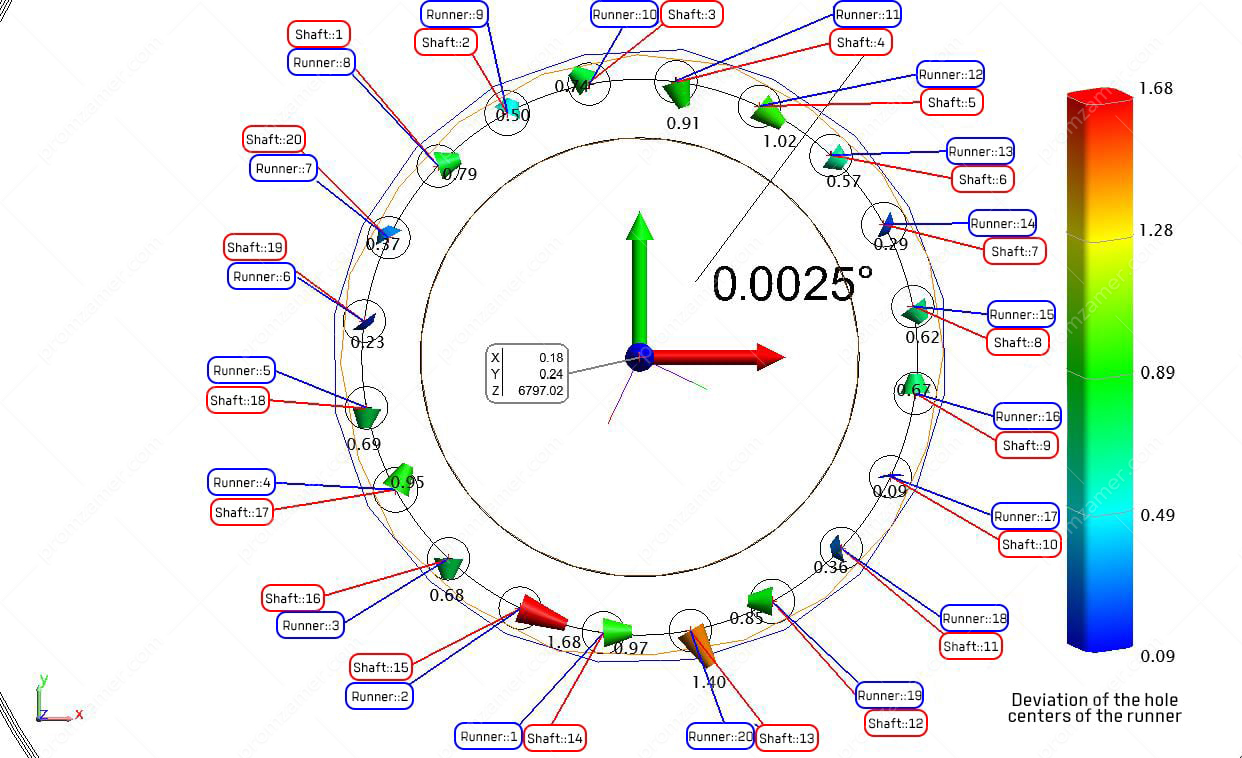
Inspection of large-sized parts and components of hydraulic units during acceptance
Замеры рабочего колеса при приемке на площадке изготовителя.
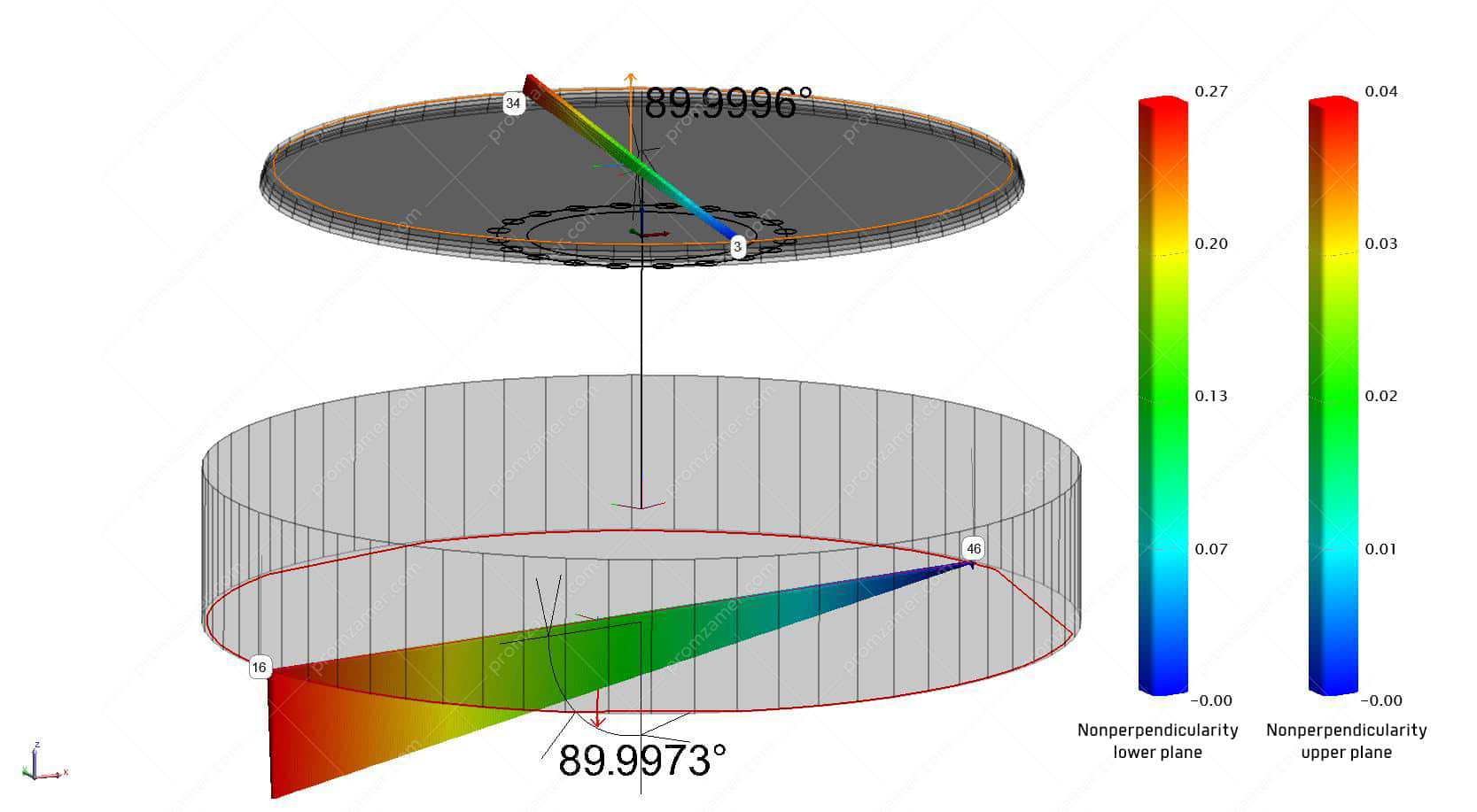
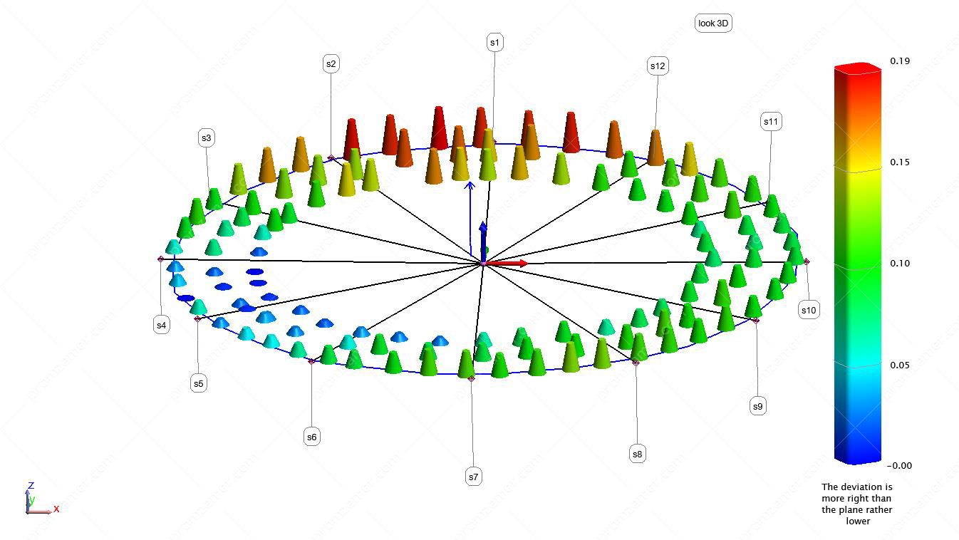
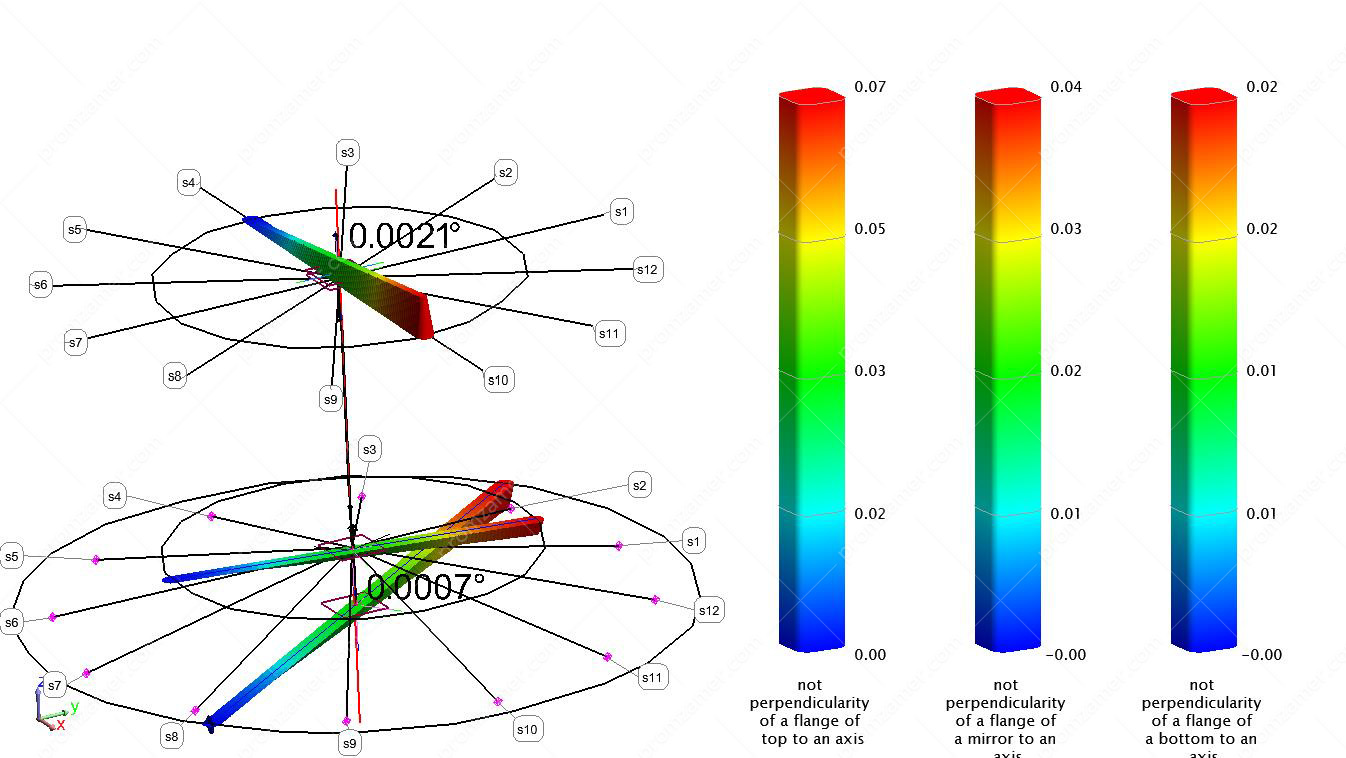
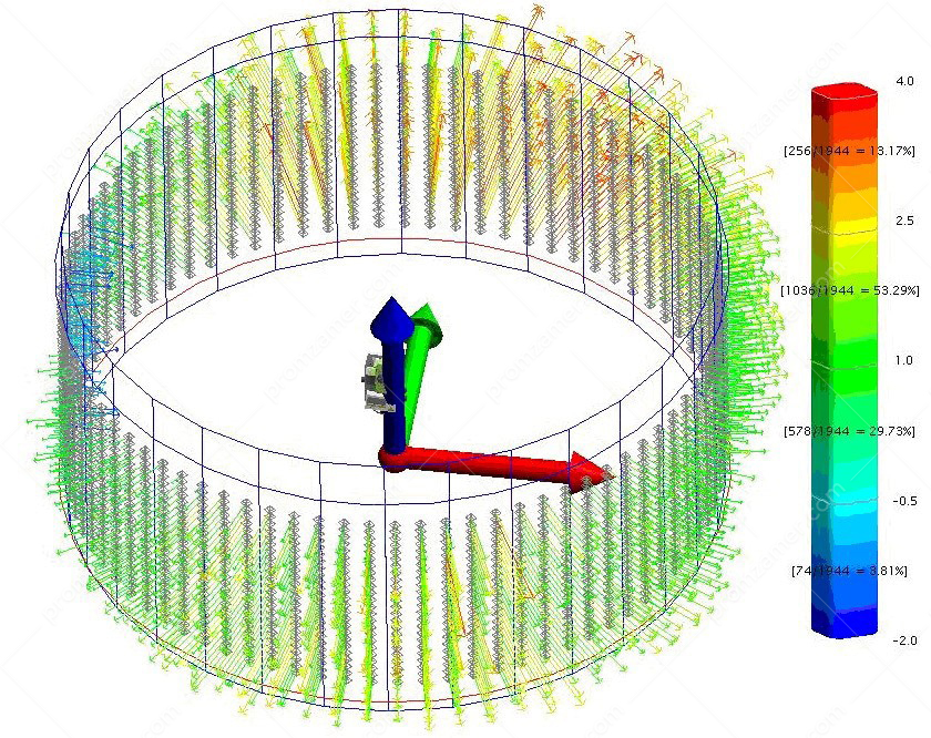
Non-perpendicularity of the upper and lower rim to the runner axis.
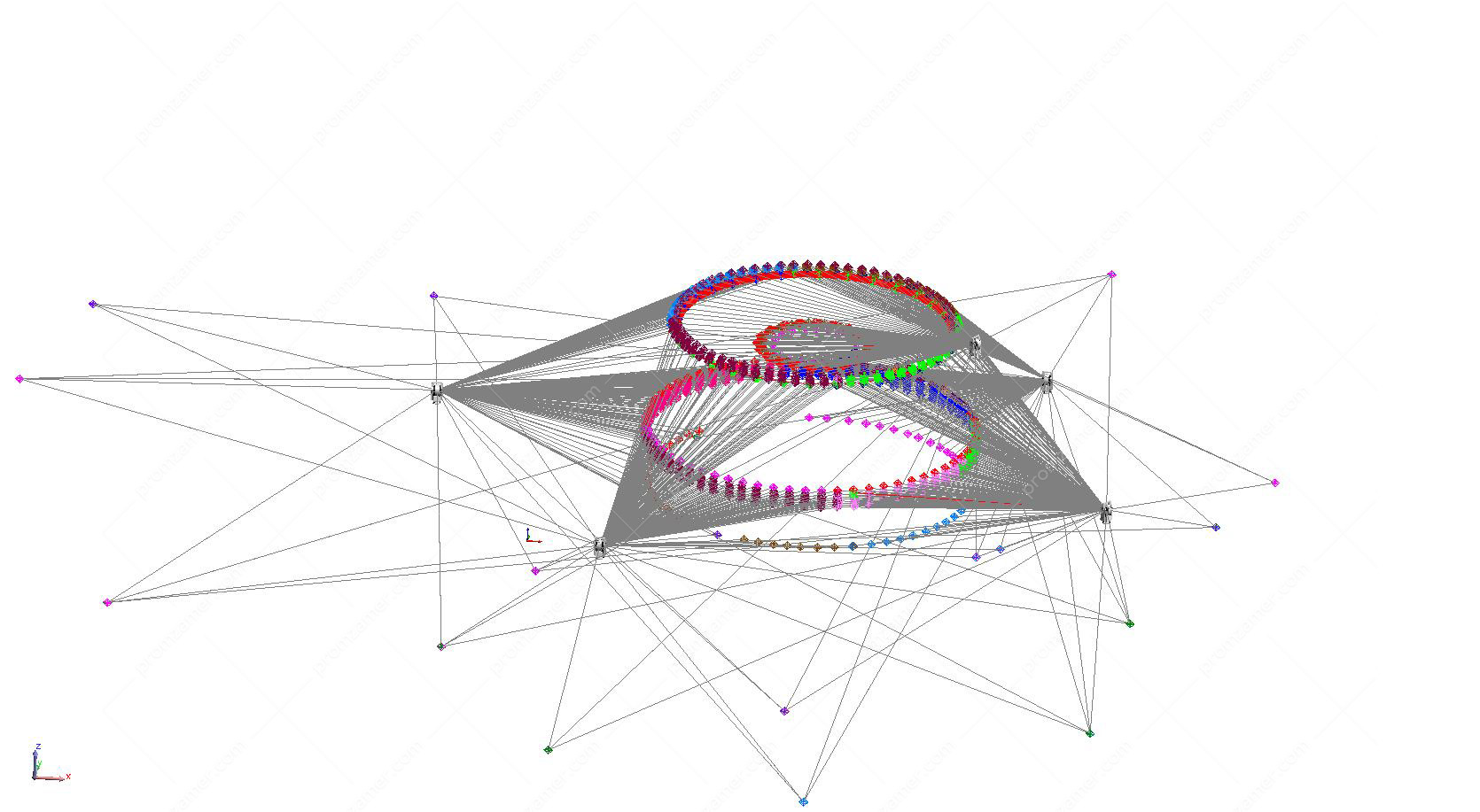
Общий вид полученных данных.
Radius deviation.
When upgrading a hydropower plant, all components and assemblies to be replaced are remanufactured, typically, by third-party contractors. During acceptance of a part or an assembly from a contractor, it is virtually impossible for an HPP (hydropower plant) representative, or it takes a lot of effort and time, to assess their quality of manufacture for geometric conformity by using traditional measurement methods.
It is a great advantage to identify all possible manufacturing nonconformities before signing the acceptance certificate, and it makes it possible to rectify the situation on the spot, which is always easier and cheaper.
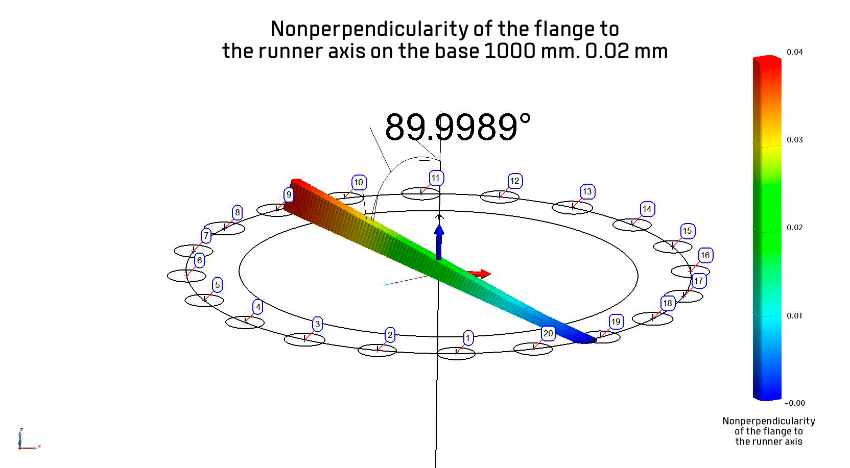
Non-perpendicularity of the upper flange to the runner axis.
The use of a laser tracker for installing the stator wedges of a large hydrogenerator
One of the conditions for the effective operation of large hydrogenerators is to comply with the design geometry of the stator core and rotor. Given the high accuracy requirements (0.05 mm) and the significant dimensions (Ø 10–20 m at a height of up to 3 m) of these mechanisms, the solution of this problem requires using accurate and advanced methods of measurement, adjusting and fixing the position of structurally important stator elements, factoring in and minimizing impact of a significant number of error sources on the measurement results.
A pre-prepared CAD model makes it irrelevant to separate into basic and intermediate wedges.
The measuring system can determine the deviation from the design position and orientation of any wedge.
A high degree of automation and measurement speed allows for real-time alignment by observing the deviation from the design position of the wedge according to data on a computer screen. Deviations can be minimized and immediately fixed by spot welding.
Thanks to a laser tracker and experience of our professionals, we can perform a wide range of measurement tasks that arise during the creation, installation and subsequent maintenance of stators of large hydrogenerators and hydraulic units in general.


Статор на монтажной площадке.
Virtual assembly technology allows you to preliminarily estimate the expected deviations of large-sized mechanical engineering objects at the manufacturer’s site without delivering them to the installation site and, if the product parameters are nonconforming, minimize their negative impact in the factory.
Thereby, we can avoid a very costly delivery and pre-assembly of the object.
The hydraulic turbine runner and its coupling with the shaft are critical elements in the hydropower sector, since this is the initial link in the assembly of the hydraulic turbine shafting. The shaft length often exceeds five meters.
Thus, the plane of the flange on the runner should be as perpendicular to the runner axis as possible, while on the shaft, the plane of the flange should be perpendicular to the shaft axis. Slight deviations of these planes from the perpendicular position to the axes of the elements may result in significant runout errors when assembling the shaft–runner pair.
The task of assembling newly manufactured elements with those already used requires a more detailed calculation and analysis of dimensional chains, since the parts used for decades were manufactured using other technologies and may differ from the current requirements. Still, they can be used as they have retained their technical and mechanical properties, and a slight nonconformity can be compensated by manufacturing a new mating part that will be coupled with it.
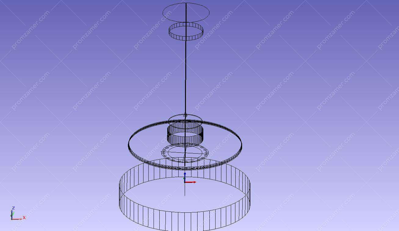
Виртуальное совмещение вала и рабочего колеса.
Общий вид полученных данных при измерениях рабочего колеса на площадке завода-изготовителя.

Общий вид полученных данных при измерениях вала на монтажной площадке ГЭС.
Above is an example of virtual coupling of the runner shaft manufactured in the 1970s, which can still be operated. However, modern conditions dictate new requirements for efficiency and intervals for repair and recovery work for HPPs. The old runner does not meet these requirements. Therefore, a new runner has been manufactured.
Our professionals measured the shaft at the HPP’s installation site. Then the runner was measured at the manufacturer’s installation site (which is located several thousand kilometers from the HPP). Slight deviations were detected during the measurement of the runner and the shaft. However, following the virtual assembly of the runner–shaft pair indicating the best position for assembly fitters, it was confirmed that, firstly, the runner and the shaft would be assembled without changing the assembly technology, and secondly, that during assembly they would meet the technical and accuracy requirements for the runout and the slope of the shaft axis relative to the runner axis. Further, with a virtually assembled runner–shaft pair in place, we placed it in the runner chamber, which was previously measured at the HPP. This allowed us to calculate the clearance between the runner and the runner chamber with an accuracy of ±0.05 mm. We identified the areas where clearances exceeded specified tolerances and took measures in advance to minimize these deviations.
Worst shaft position on the runner.
Best shaft position on the runner.
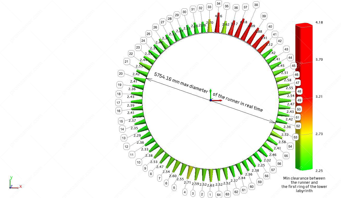
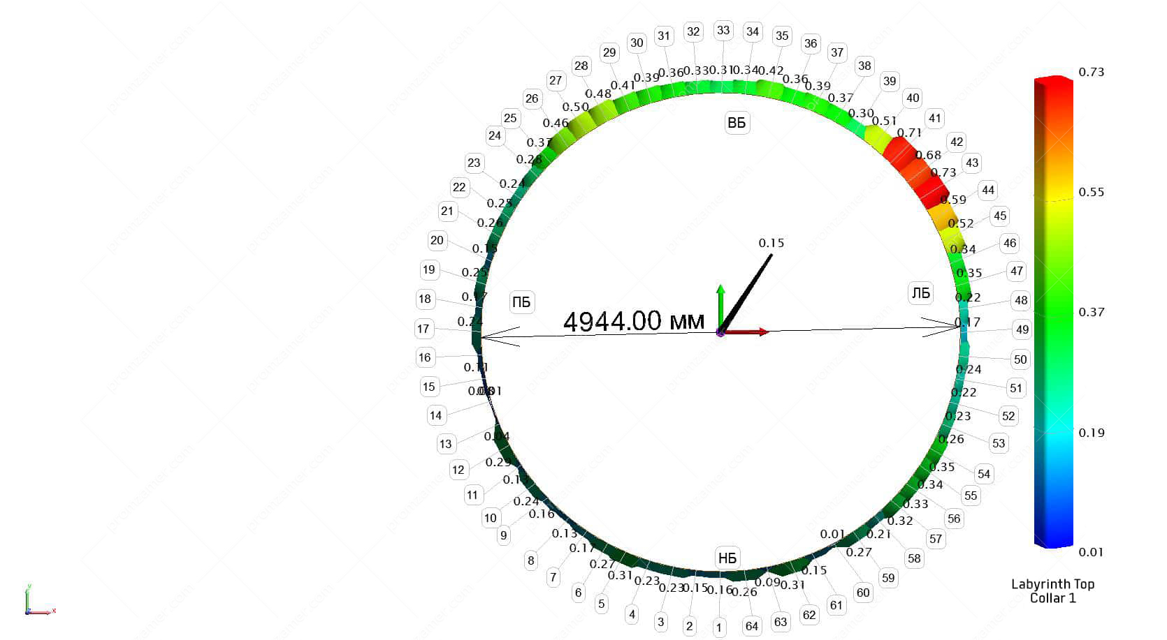
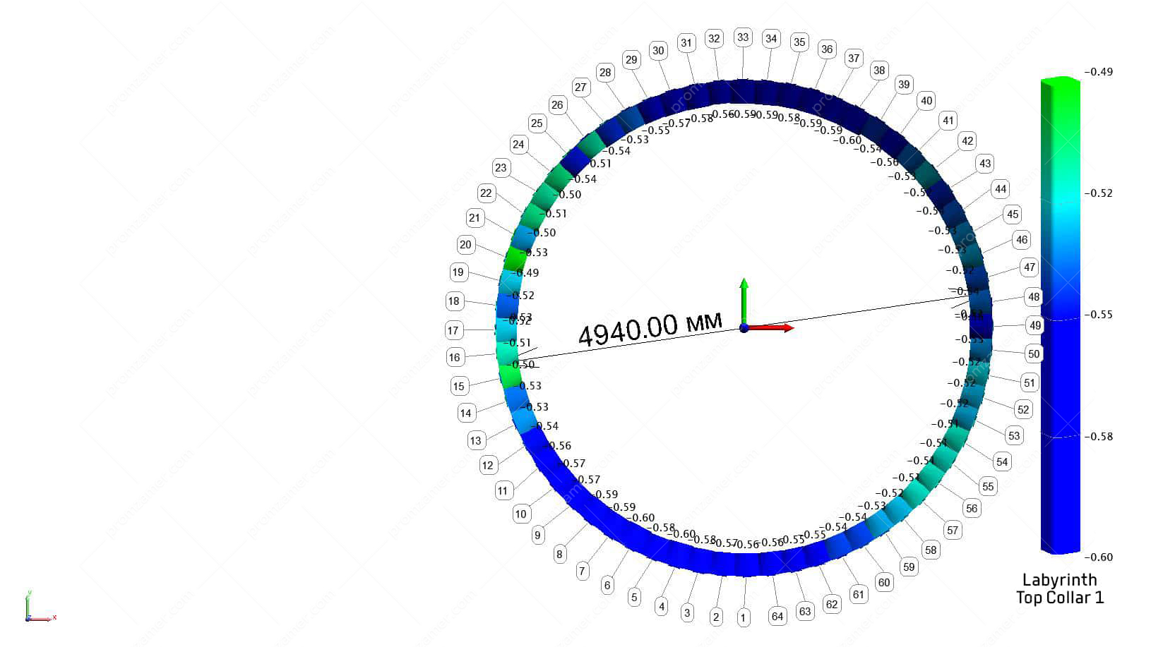
Chart of the expected clearance between the runner and the flow part of the lower labyrinth seal.
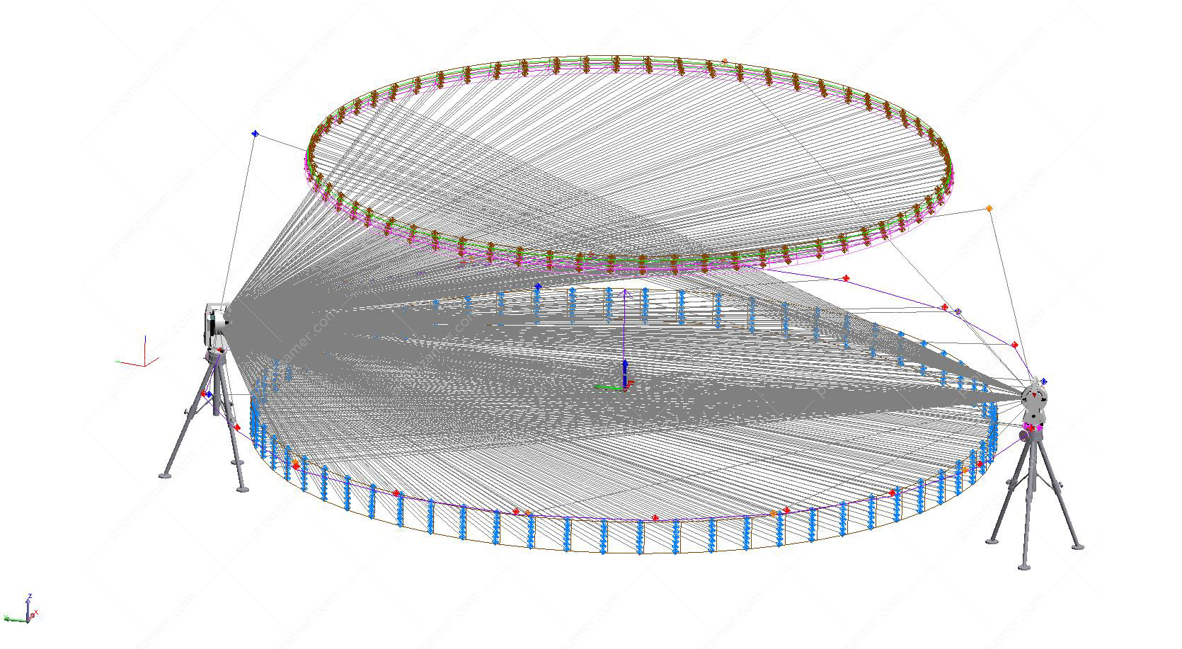
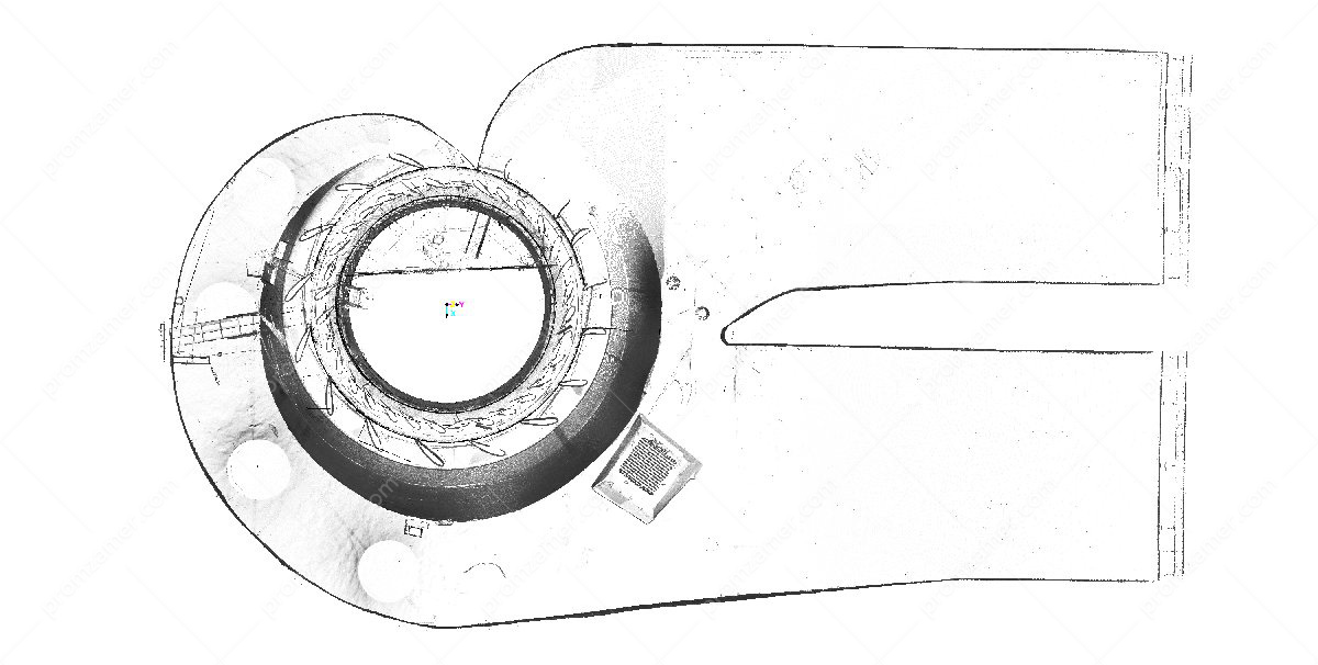
3D laser scanning
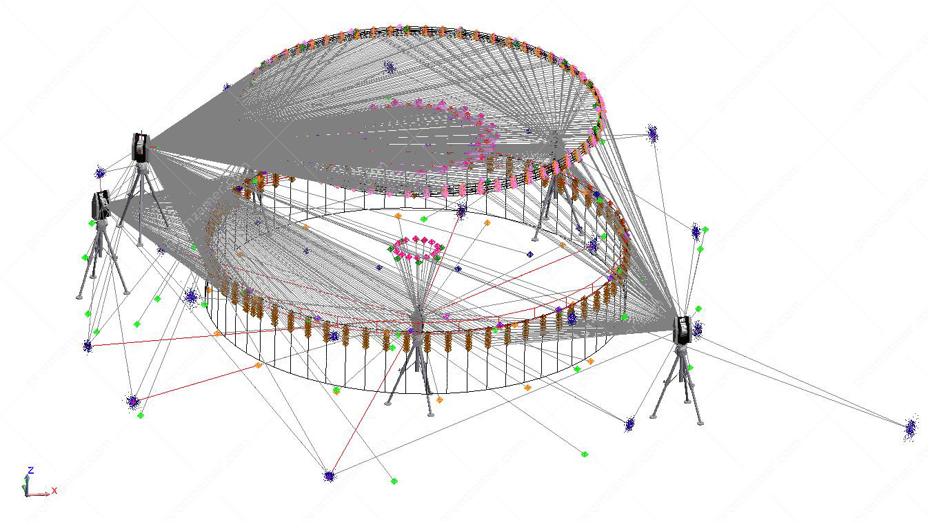
3D laser scanning is a technology that allows you to contactlessly determine the spatial coordinates of a large number of points on the surface of the measured object, the so-called point cloud. This instrument uses the polar principle to determine the points: angle sensors measure horizontal and vertical angles, a phase laser range finder measures distances.
Most commonly, when scanning complex objects, surveying from one instrument station is not enough as only a part of the surfaces of the object being measured falls into the scanner’s working range, so several stations have to be used. Scans from different instrument stations are then consolidated into a single coordinate system using special benchmarks whose coordinates are determined with higher accuracy.
The illustrations show scans of a turbine runner made by Surphaser 25HSX.
Laser scanning technology may be in demand:
- to inspect the shape of complex surfaces (hydroturbine blades, runner chamber, spiral casing, water supply and discharge);
- to determine the magnitude of defects in steel lining or concrete encasement;
- during construction, to identify design deviations;
- to build models and draw up dimensional drawings of an object in preparation for upgrade;
- to observe the deformation of an object under various influences;
- during virtual assembly of a large-sized object;
for overall inspection (of mines and transport tunnels); - to determine the capacity of complex tanks.
The final 3D model of an object with the semantic data assigned to the elements can be exported to various CAD programs in different formats.
The 3D laser scanning technology allows you to virtually move scanned large-sized objects through scanned transport and process openings and tunnels, with clearance control at each stage.
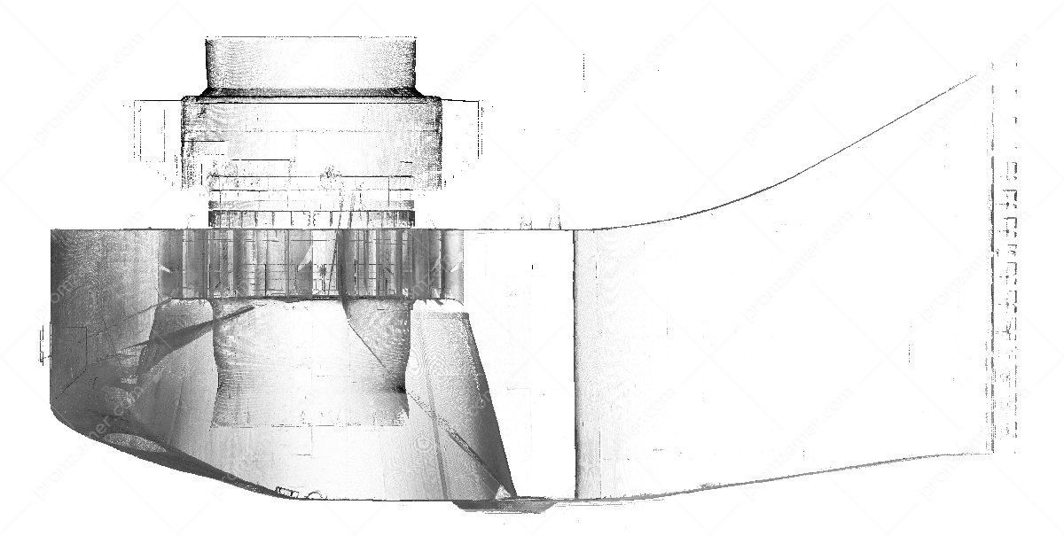
Результат сканирования – точечная модель камеры рабо-чего колеса, направляющего аппарата и спиральной камеры.

Tell us about your project
We will contact you in 1 working day and prepare the info you need.
