You are able to download printable version of this article in .pdf format for offline use!
Aviation Sector
About measurements in aviation industry
High requirements for manufacturing accuracy of load-bearing structures of modern aircraft are among prerequisites for their assembly and subsequent normal operation. The importance of meeting these requirements increases significantly in the context of broad domestic and international cooperation in the creation of the latest-generation aircraft.
Given the considerable dimensions of modern aircraft and tight tolerances during the assembly of their components, as well as modern highly automated assembly benches. The task of checking the position of the basic elements of mating structures requires the creation and efficient integration of new measuring technologies into the dimensional inspection structure established in aircraft, helicopter, space and launch vehicles sectors.

The traditional dimensional inspection methods used in the aerospace sector require the creation of a great amount of material-intensive tooling: mock-ups of various aircraft elements, templates, testing and assembly benches, jigs.
Industrial-geodetic systems are widely used by major players in Russia’s aerospace sector.
Many enterprises use laser trackers not only as a means of geometry inspection of finished products and installation of jig tooling, but also as a control of automatic assembly lines. Automatic assembly lines significantly speed up the process of joining elements, improve assembly quality, and increase the reliability of aircraft, which, ultimately, make the product more competitive in the market.
Installation of jig tooling
Similar to other mass production sectors, assembly benches and jig tooling are indispensable in the aircraft construction. Old methods for installing jig tooling involved references, full-scale mock-ups, templates, special casting stands. Working with reference technologies requires large storage premises, continuous geometry inspection of references and their removal for scheduled maintenance on workbenches. Failure of one subassembly on a bench requires a new reference, which takes several days to several weeks to install, with the company sustaining losses in the meantime.
Our professionals are well experienced in installing aviation and aerospace jig tooling, leveling and geometry inspection of aircraft, and developing measurement concepts for the aircraft construction.
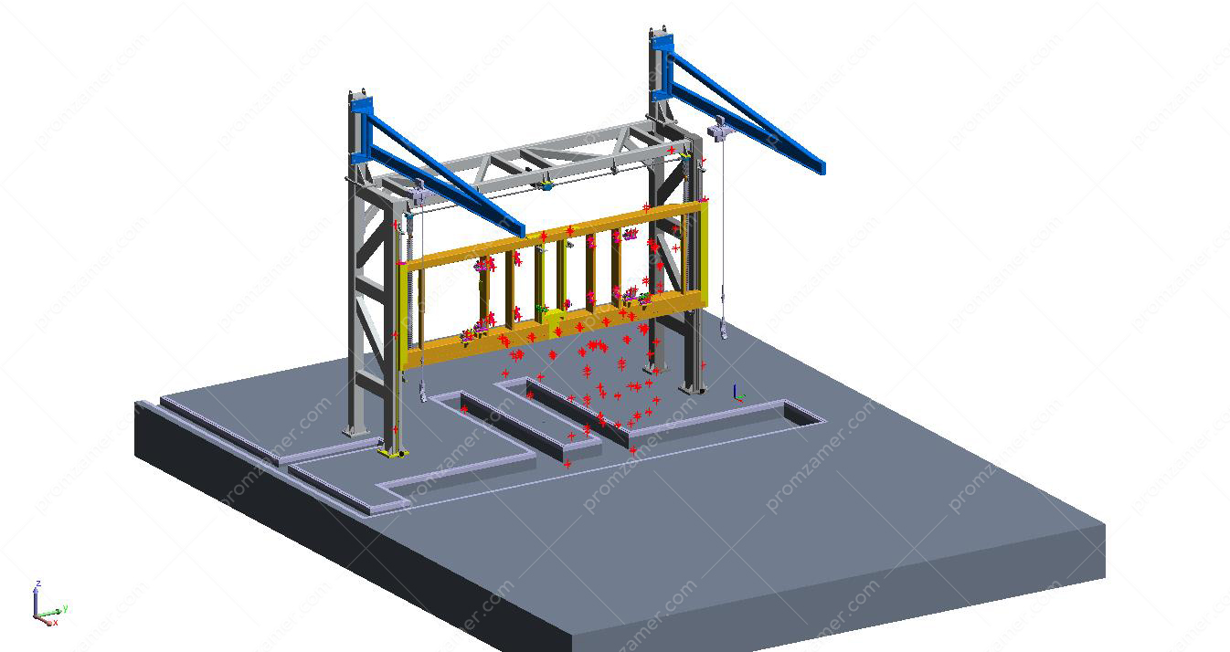
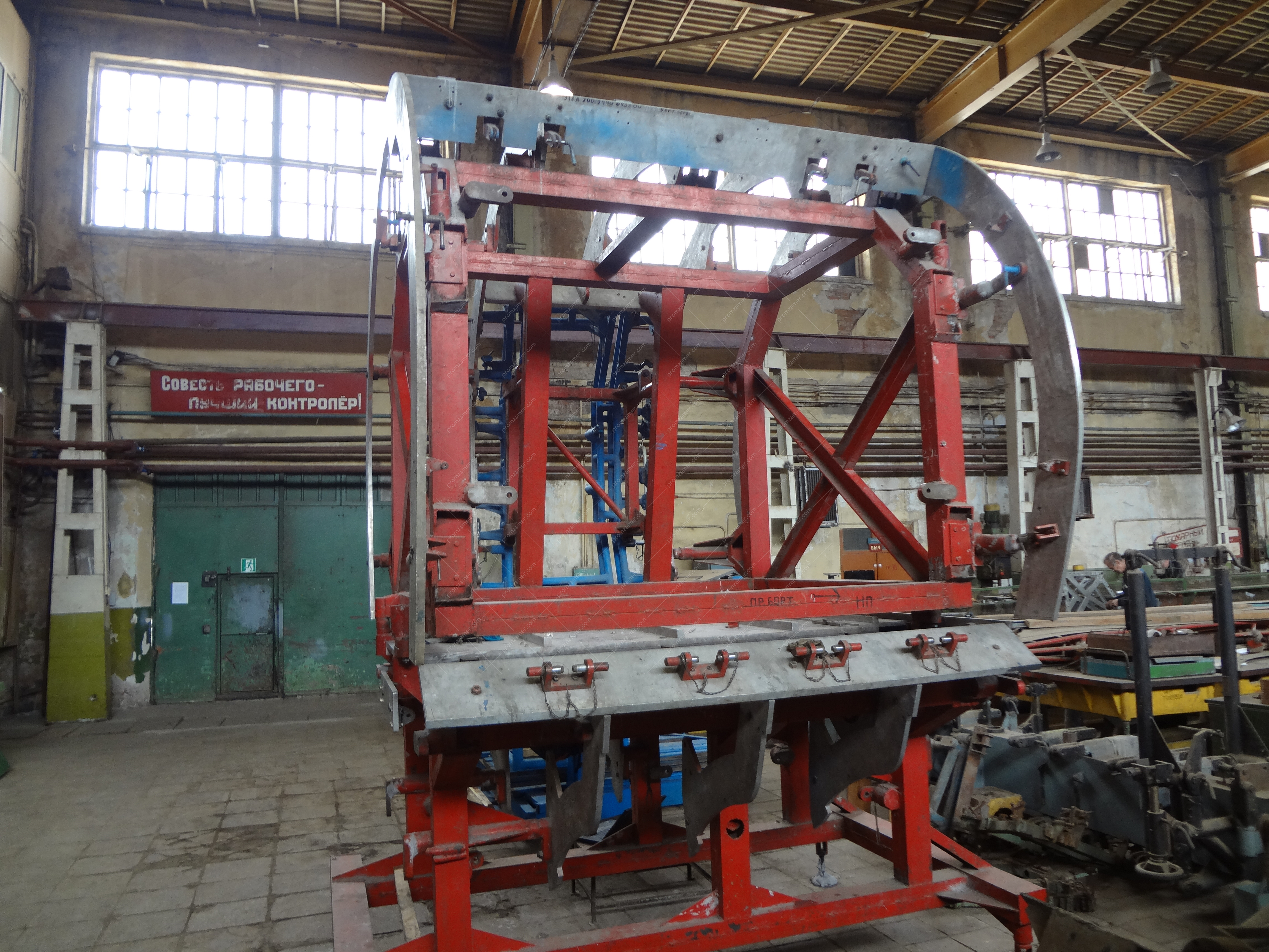
Модель стапельной оснастки с контрольными точками для измерений.

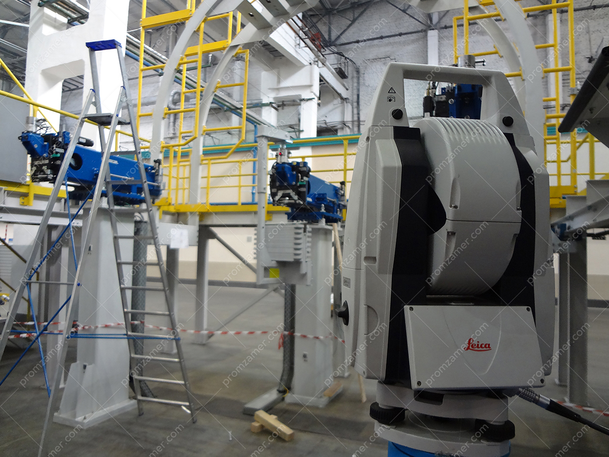
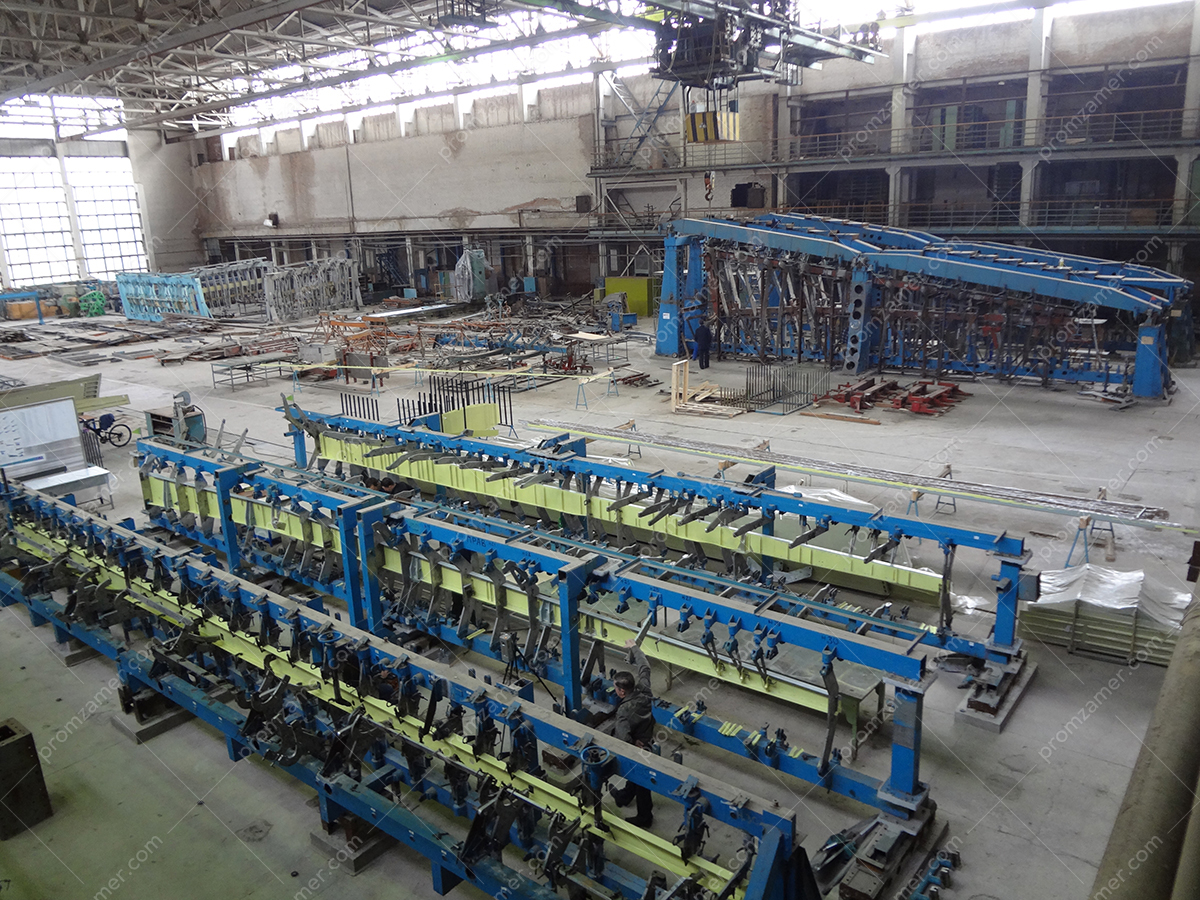
Смонтированная оснастка.

Общий вид стапельной оснастки для сборки крыла. Оснастка разрабатывалась под монтаж эталонным способом.
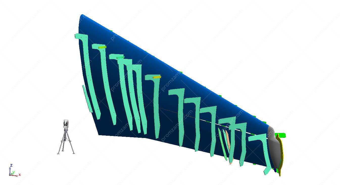
CAD-модель получена от заказчика, использовалась для монтажа без эталонным методом.
We use laser trackers for jig tooling installation and geometry inspection. As a reference, we use a 3D model of a jig or an aircraft. A referenceless technology significantly speeds up the installation process, improves its quality and requires fewer maintenance personnel in the future.
With many years of experience, we offer in-house solutions and techniques for jig tooling installation using laser trackers, even the tooling that was developed for a reference method.
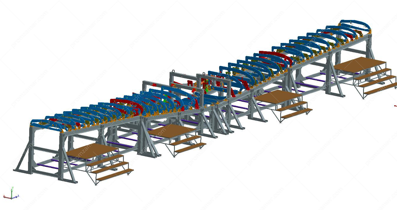
Модель сборочной оснастки крыла.
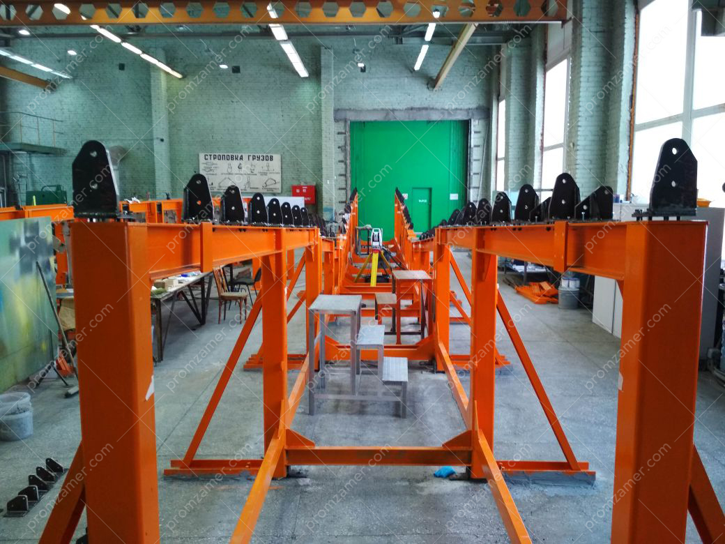
Начальный этап монтажа сборочной оснастки крыла согласно модели заказчика.
If a subassembly fails, it can be quickly, in a few hours, set in the nominal position. The use of a referenceless technology also increases the flexibility of jig tooling, allows for design changes without high costs and in shortest time.
During scheduled repair work that takes place once a year, it is enough to inspect all tooling elements in checkpoints or by contours, which does not take much time, and adjust only those elements that do not meet the specified tolerance defined by the design documentation.
Geometry inspection of a product
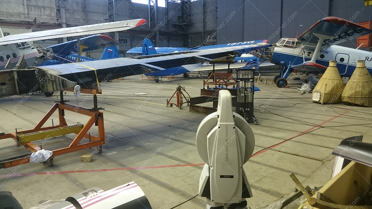
Experience in the use of positioning systems shows that a total station, a tracker, and a measuring arm successfully complement each other, and together they can solve the widest range of measurement tasks in the most challenging production conditions.
Our team of professionals are ready to tackle any measuring task in the field of spatial measurements your company may face, select the necessary equipment to solve the task at hand, or optimize and/or automate existing measurement methods.
Examples of work done:
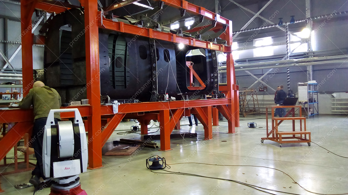
Измерение отсека в стапеле для дальнейшего обеспечения стыковки. В дальнейшем полное метрологическое сопровождение стыковки.
Контроль, оцифровка эталонов, шаблонов, макетов.
Готовое изделие.

Измерение узлов навески крыла с использованием КИМ типа «рука».
Leveling of airplane, helicopter and other aircraft

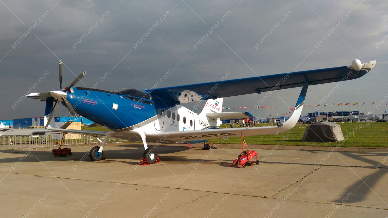
Нивелировка самолета.

Измерение и разметка прочих запускаемых аппаратов.
Нивелировка самолетов.
The purpose of leveling is to inspect geometry and adjust flight controls. The leveling results are recorded in the leveling passport.
On a leveling diagram, geometric parameters are expressed in terms of the coordinates of the special leveling points in the form of center marks.
With extensive experience in the aircraft construction, our professionals can level any aircraft for your production needs.
We can develop leveling concepts based on your drawings or do the job using a ready-made solution.
Laser scanning
Laser scanning is one of the promising areas in metrology. 3D laser scanning is a technology that allows you to contactlessly determine the spatial coordinates of a large number of points on the surface of the measured object, the so-called point cloud. For each point of this cloud, in addition to spatial coordinates, the intensity of the reflected signal is also recorded, which, in the future, helps recognize contours and automatically detect the centers of special contrast targets.
In general, when scanning complex objects, surveying from one instrument station is not enough as only a part of the surfaces of the object being measured falls into the scanner’s working range, so several stations have to be used.
Scans from different instrument stations are then consolidated into a single coordinate system using special benchmarks whose coordinates are determined with higher accuracy.
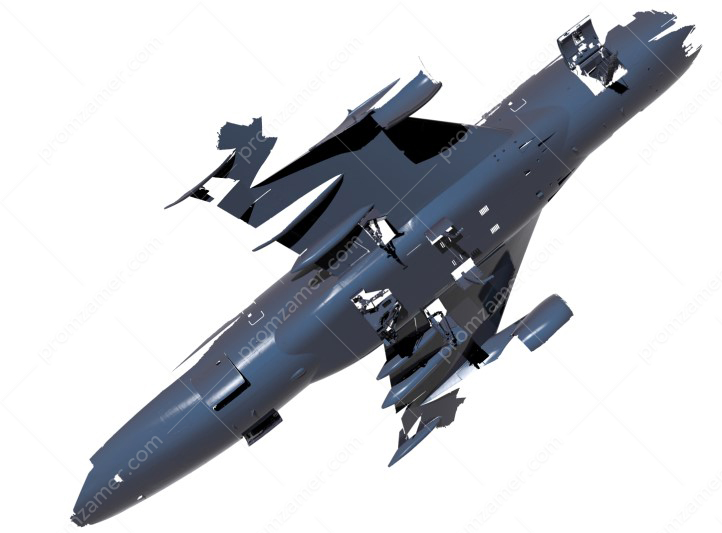
Фрагмент скана самолета.
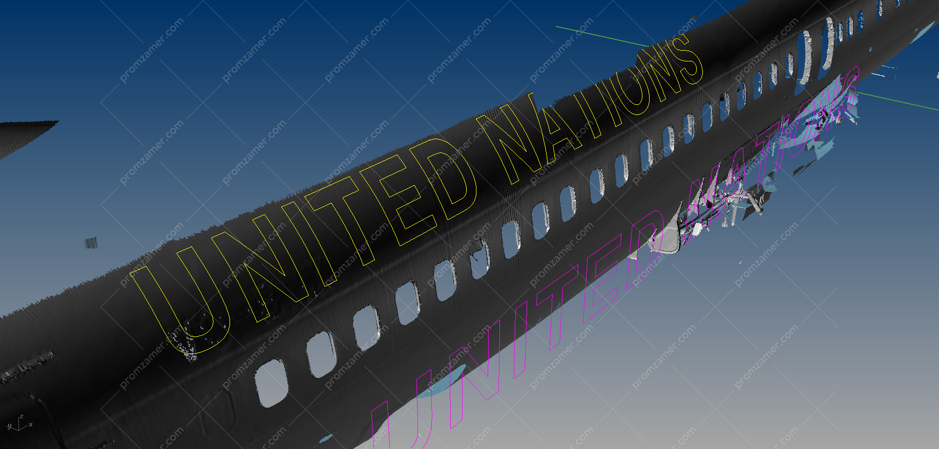
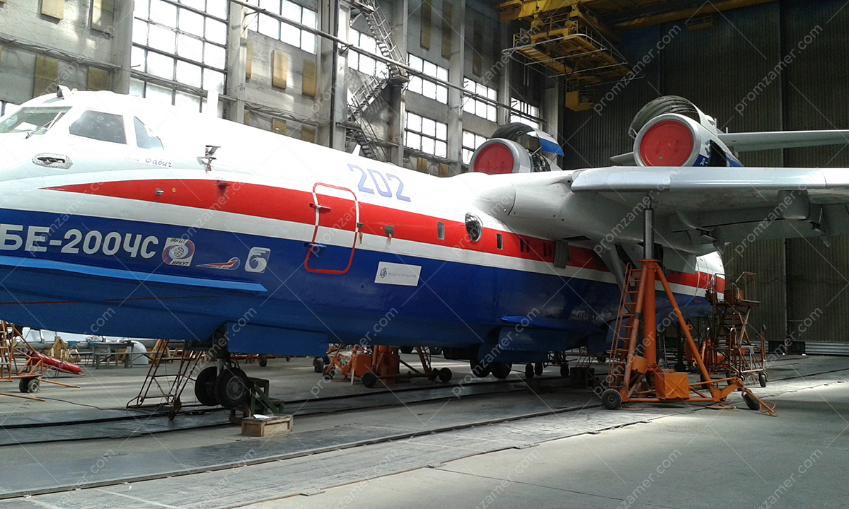
Сканирование части фюзеляжа для получения поверхности под проецирование кривых.
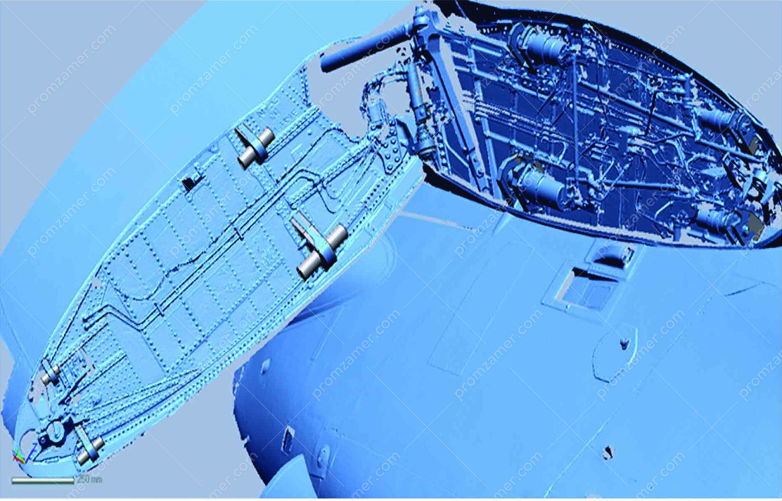
Скан фрагмента узлов крепления.
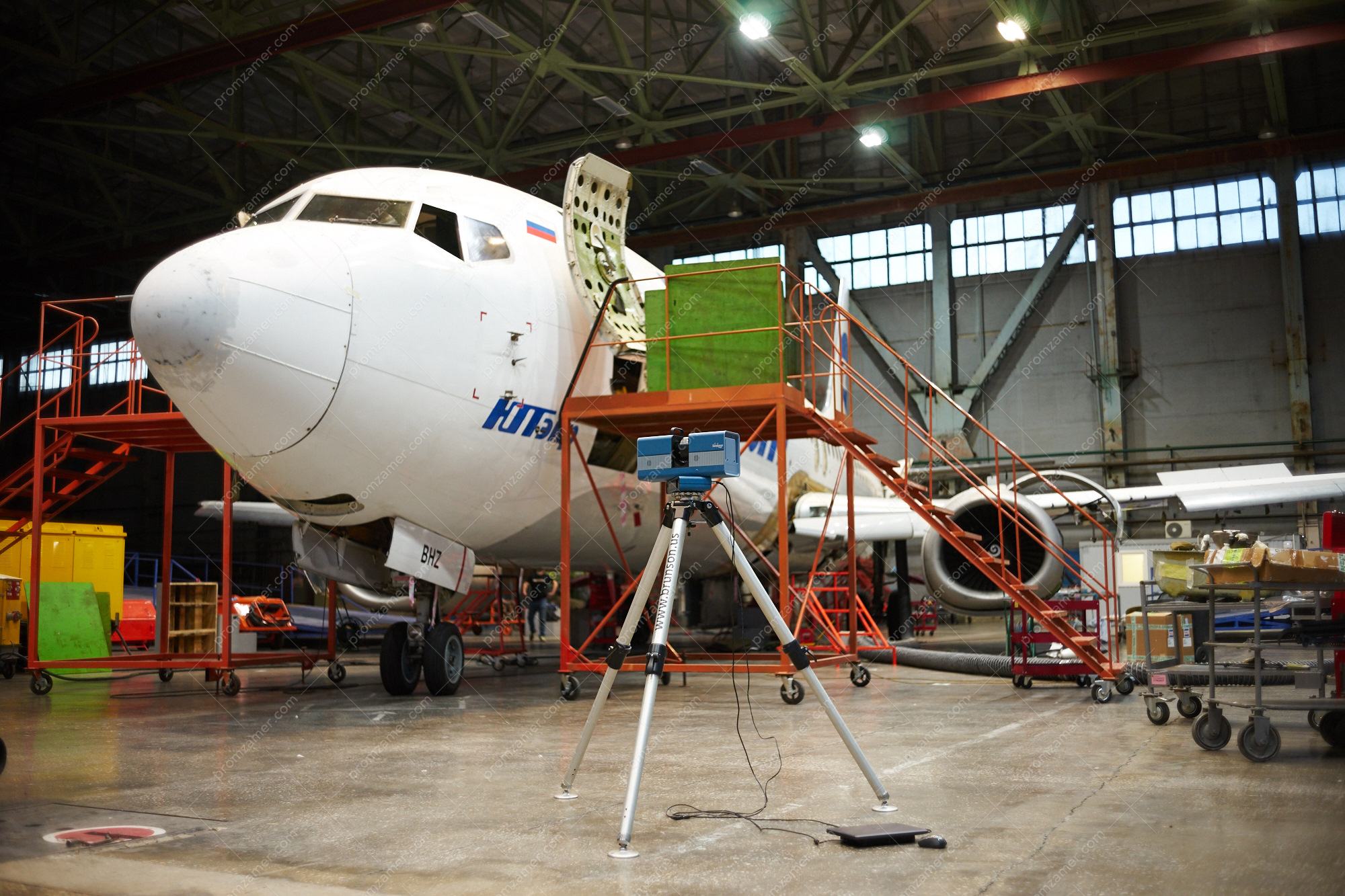
Общий вид сканера.
Scanned objects represent point clouds, and how they will be used further depends on tasks at hand. Typically, it is required to compare the resulting point cloud with a CAD model and inspect the geometry of the object shape. Just as typically, the problem of reverse engineering is to be solved when there is a need to obtain a CAD model from a point cloud. Having a CAD model of an engine and a nacelle, for example, in a single coordinate system, it is possible to virtually place the engine in the nacelle, with clearance control at each stage. There is a large number of such tasks in aviation, especially at the stages of introducing a new product or redesigning an existing one.
Laser projection systems
Laser projection systems are widely used in the aviation sector. In our work, we use laser projection systems produced by LAP Laser. We are also ready to supply these systems to your business as well as commission the equipment and train your personnel on how to use this equipment.
Application of projection systems in the aerospace sector:
- composite lay-up;
- marking contours for painting on curved surfaces;
- projecting hole centers;
- projecting installation positions of elements on aircraft panels and products;
- other marking with projection onto any surfaces that may be needed for your business.
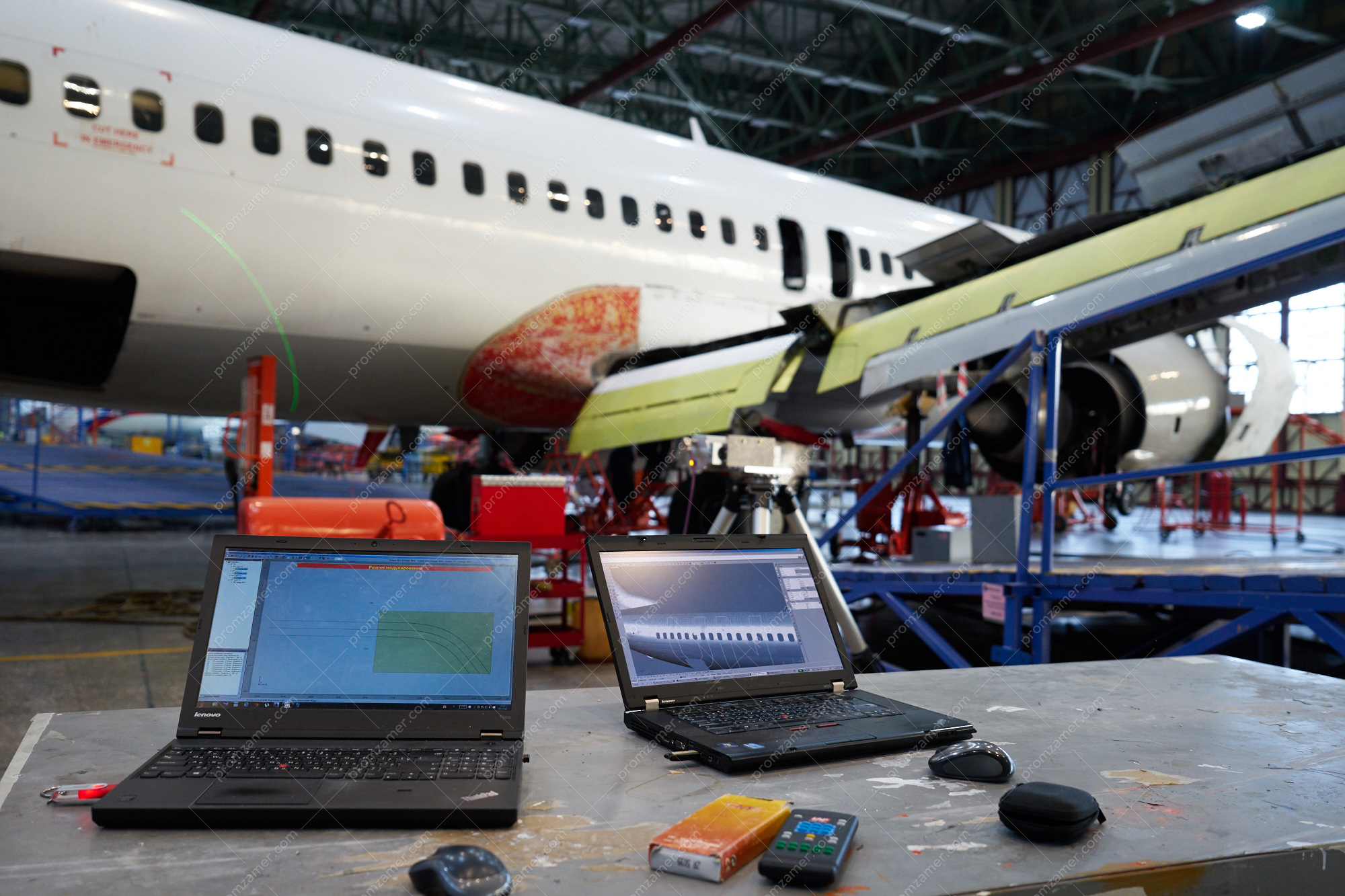
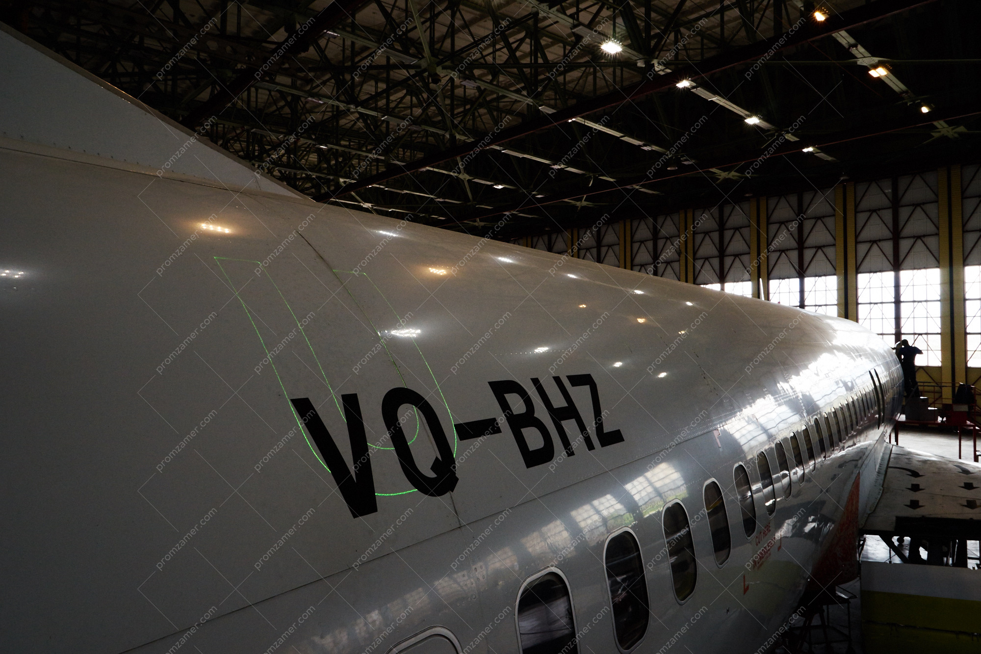
Проецирование фрагмента окраски на фюзеляж самолета.
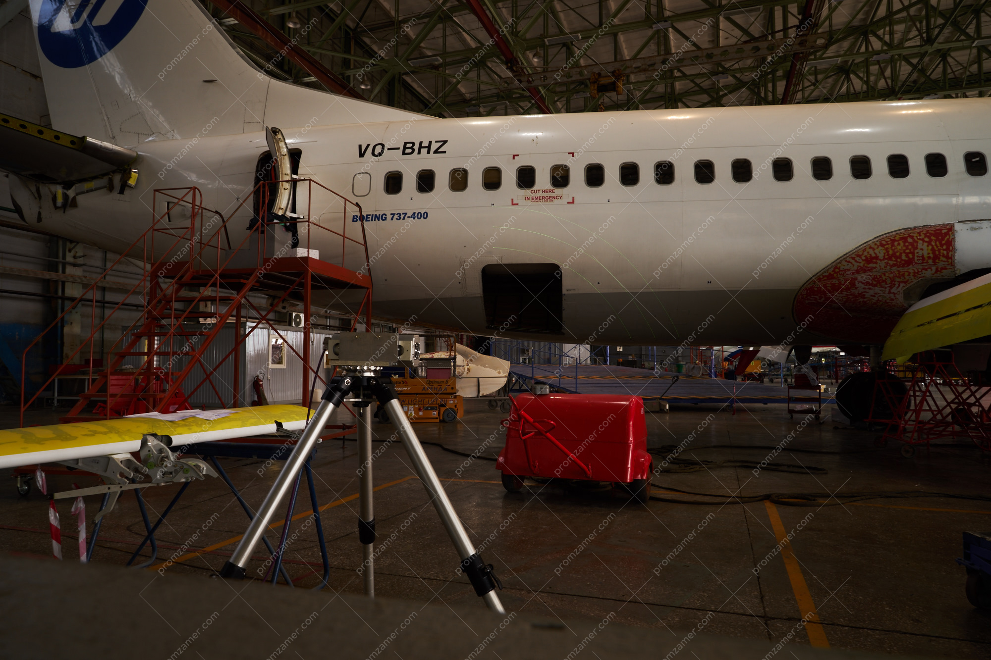
Общий вид проекционной системы в работе.
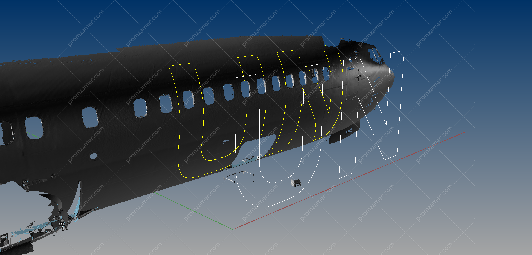
Перед проецированием была отсканирована и получена форма поверхности фюзеляжа.
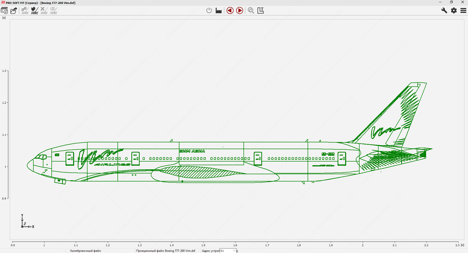
Пример подготовленного файла для проецирования кривых на поверхность.
Tell us about your project
We will contact you in 1 working day and prepare the info you need.
