You are able to download printable version of this article in .pdf format for offline use!
Metallurgy
Alignment of Continuous Casting Machine
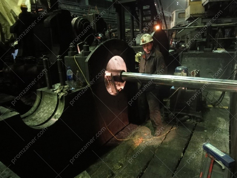
Due to high energy saving, the relative compactness of the location of main components and mechanisms, and as a result of the low cost of finished products, continuous casting machines (CCM) are becoming increasingly popular in metallurgy. One of the features of the CCM is the high accuracy requirements for installation of the machine rollers, especially in its curved part.
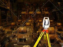
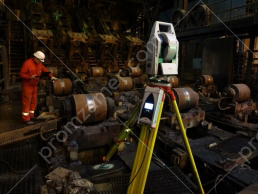
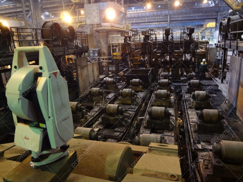
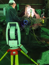
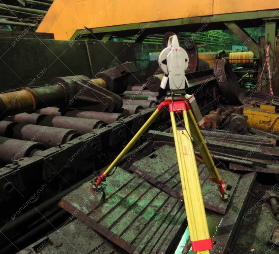
Our professionals have mastered the method using modern industrial-geodetic positioning systems, which allows for aligning and adjusting any continuous steel casting machine in the shortest possible time. The use of the Leica AT402 high-precision mobile absolute laser tracker with a set of state-of-the-art measuring equipment allowed us to complete the entire scope of work with high accuracy.
During the measurements, we obtained data on the location of each roller, its shape and diameter. We defined the values of the deviations of the rollers from the design position. Based on the data received from our professionals, the repair personnel easily installed equipment with an error not exceeding the permissible values. Based on the results of our measurements, the customer receives all the necessary information, such as the position of mechanisms before dismantling, after alignment and the values required for its adjustment.
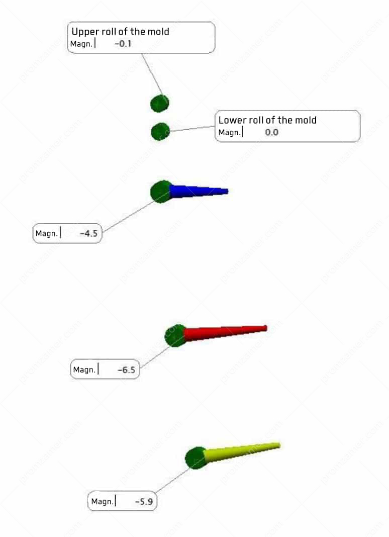
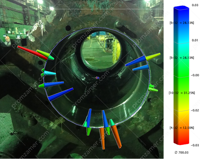
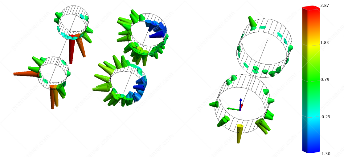
Chart of deviations of roller surfaces from the theoretical curve
Теоретическая кривая.

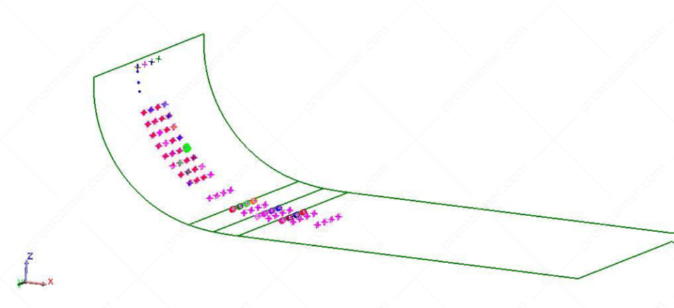
Chart of deviations of rollers’ tangential points of a segment of the design curve after adjusting the seats
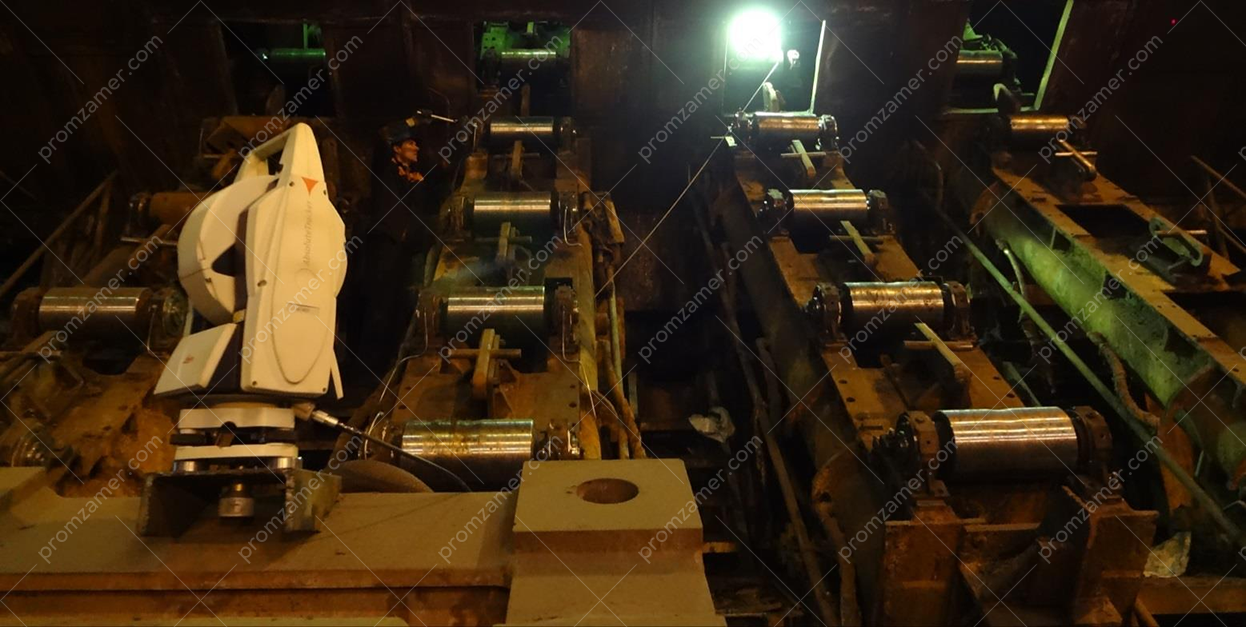
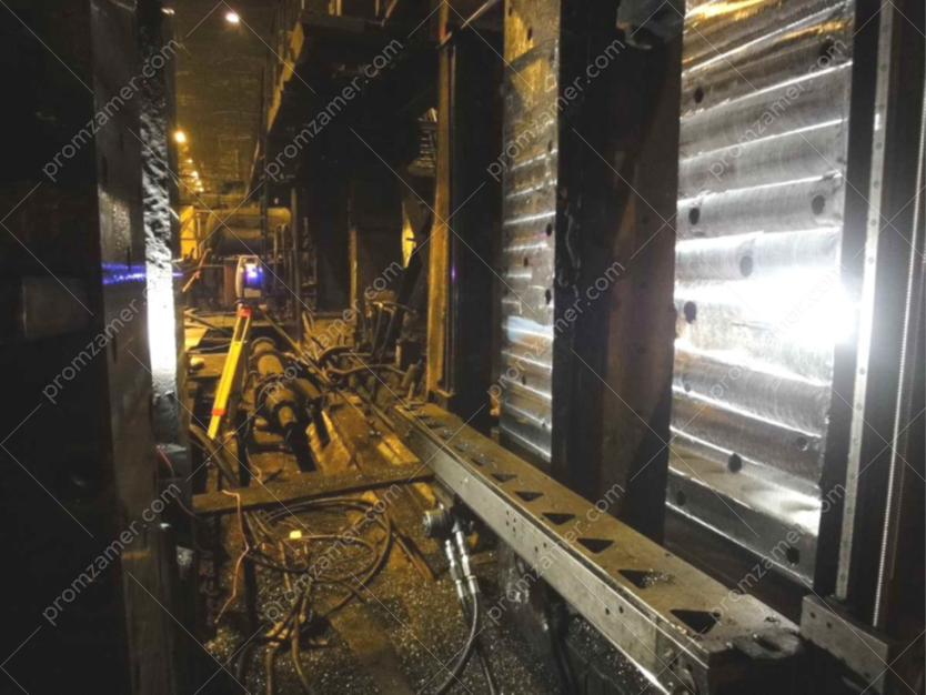
A broad working range of the instrument allowed us to easily measure parts located at a considerable distance from each other. With the internal power supply from a battery and a built-in WLAN module, we could quickly change the location of the tracker, which in turn reduced the total measurement time. High reliability, as well as protection of the tracker against dust and water, also helped our engineers tackle the task at hand in a prompt manner.
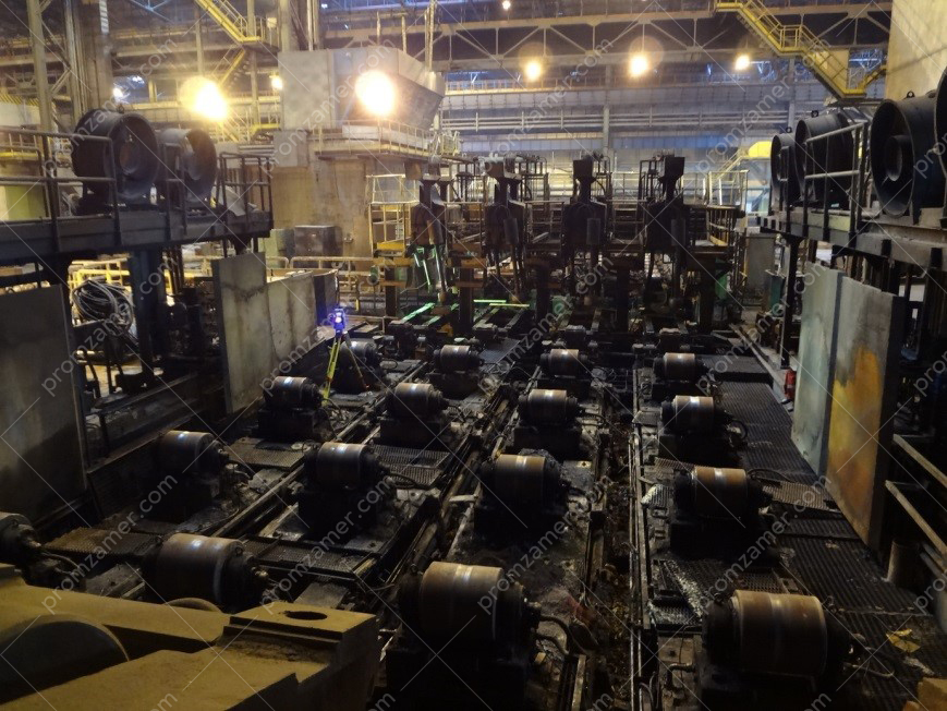
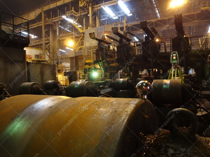
Measurement of rolling components and mechanisms
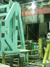
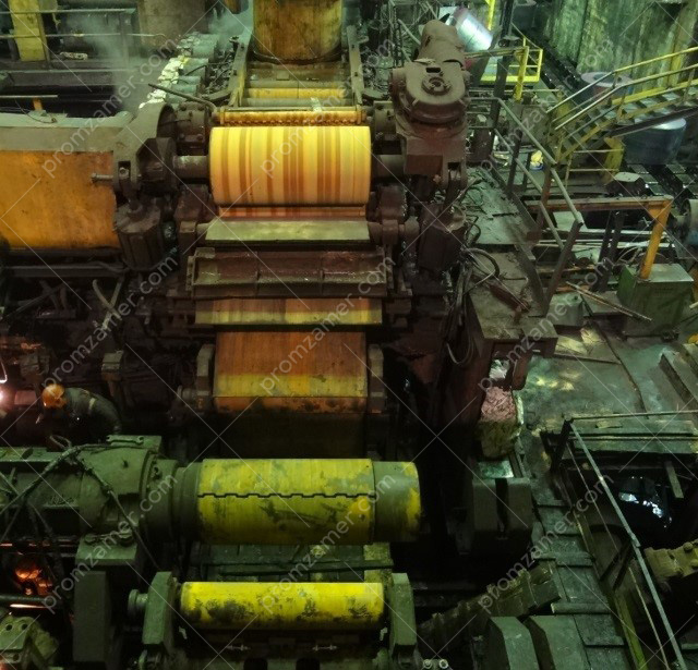
A rolling mill is a complex set of equipment that provides rolling, tilting, cutting, straightening, packaging and transportation of the final metal products. Mill mechanisms are quite numerous, and it is critical that each one of them occupies its design position as it affects the safety and reliability of the entire mill.
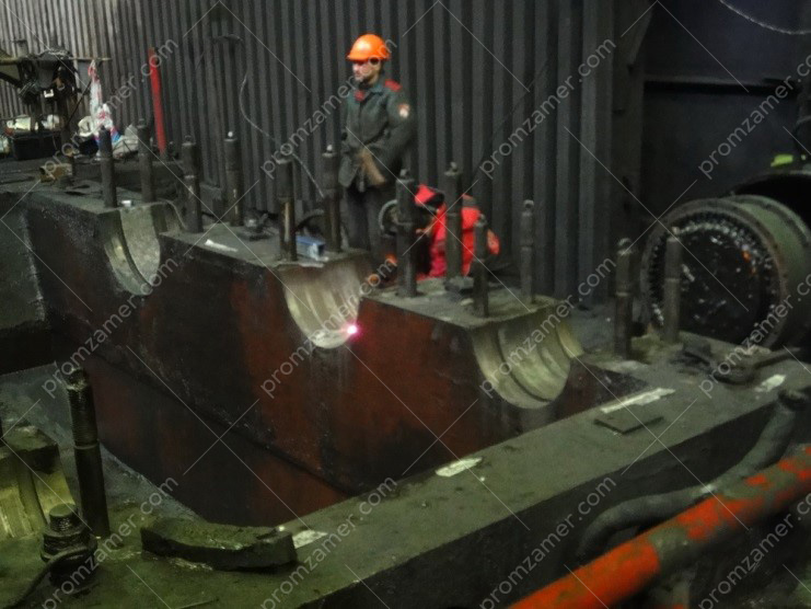
One of the main units of a rolling mill is a breakdown stand. During operation, the stand is subjected to high dynamic and static loads, which deforms its metal structure. To remedy this, a wide range of measuring work is required. The methodology for such work has been developed and is being successfully applied by our professionals at many steelworks. This work includes determining the position of the rolling axis, the axes of each stand, bars and hydraulic units of the stands, and more.

Картограмма отклонений поверхностей станин от теоретического положения.
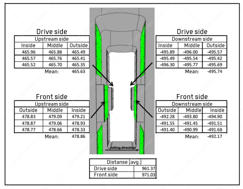
The data we obtained help the repair personnel judge the degree of equipment wear and make the right decision on the repair method. In some cases, it may be necessary to reduce the size between the bars, and in other cases, on the contrary, machine them. Our professionals carry out continuous monitoring of the entire adjustment process and pass relevant conclusions on the condition of the mechanism components.
Other equally critical assemblies of a sheet rolling mill are uncoilers and coilers. For the failure-free operation of the entire mill, it is extremely important to ensure their design location relative to the rolling axis. Based on the values that we provide, you will have no difficulty in installing equipment in the required position.
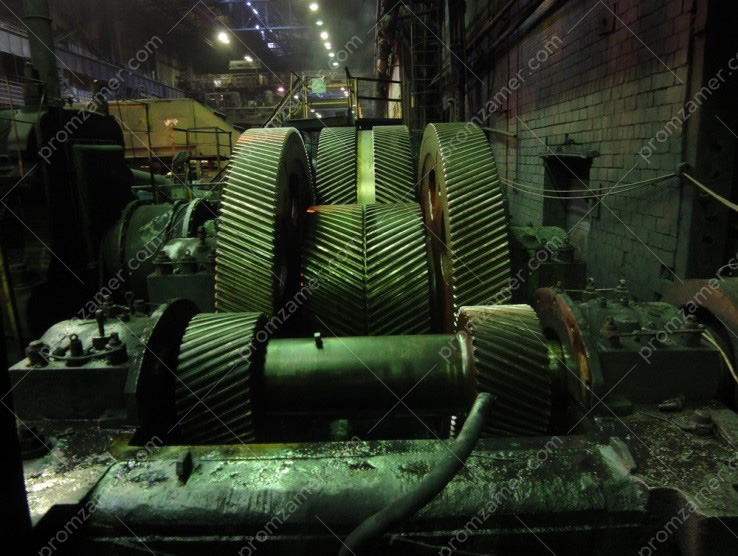
Achieving the design geometry of gearboxes
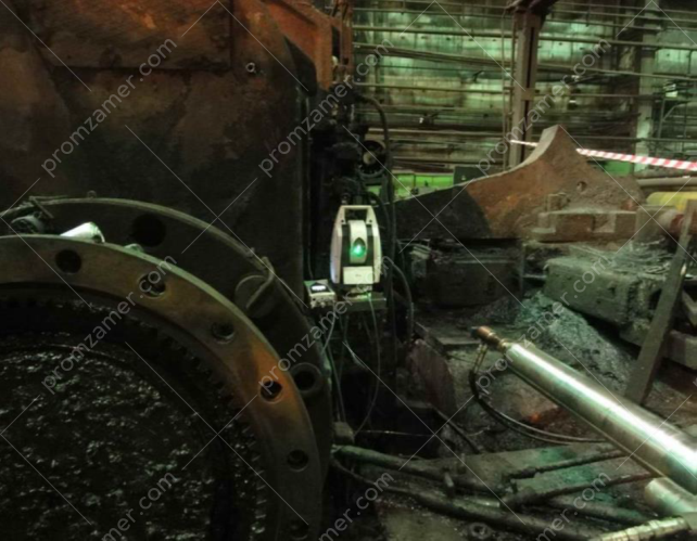
A gearbox is a mechanism, which is essential to all production operations today. Metallurgy is no exception. Rolled section, flat steel, blooms and slabs are the process stages where gearboxes are used most of all. Shaft parallelism is one of the main requirements for the failure-free and long-term operation of a gearbox. Given the dimensions of mechanisms, it is not always easy to achieve this in the metallurgical production conditions. Over time, the bearing seats of gearbox shafts wear out under the action of high loads, which affects the parallelism of the shafts. In turn, it adversely affects the operation of the gear train, which increases the vibration and load on the bearings. This cycle is continuous. To stop it, the gear pair needs replacing. However, it is extremely impractical to install new shafts in old seats because shafts will remain crossed. It is costly and time-consuming to dismantle a gearbox weighing dozens of tons and move it to a mechanical repair shop. The best solution to this problem may be to machine the seats with mobile metal-cutting machines directly in the workshop. However, these machines need precise positioning in the gearbox casing.

On many occasions, our professionals have applied their expertise to repair gearboxes. The use of high-precision equipment, such as a Leica AT402 laser tracker, allows you to easily handle the whole scope of works. The list of measuring works covers the entire stage of the repair of the gearbox. These works include aligning anchor plates, surveying the seats of the bearing assemblies of gearbox shafts immediately after their dismantling, issuing recommendations on how to address nonconformities with design documentation, adjusting the position of a metalworking machine, measuring the seats after machining.
According to statistics, up to 40% of bearing failures result from misalignment of mechanisms. Misalignment is caused by insufficient alignment of mating components. To ensure reliable operation of mechanisms, all their components are aligned in accordance with the accepted tolerances. On multiple occasions, we have performed work to align large-sized equipment, and the high accuracy of the measuring equipment we use makes it easy to carry out alignment to two decimal places of a millimeter.
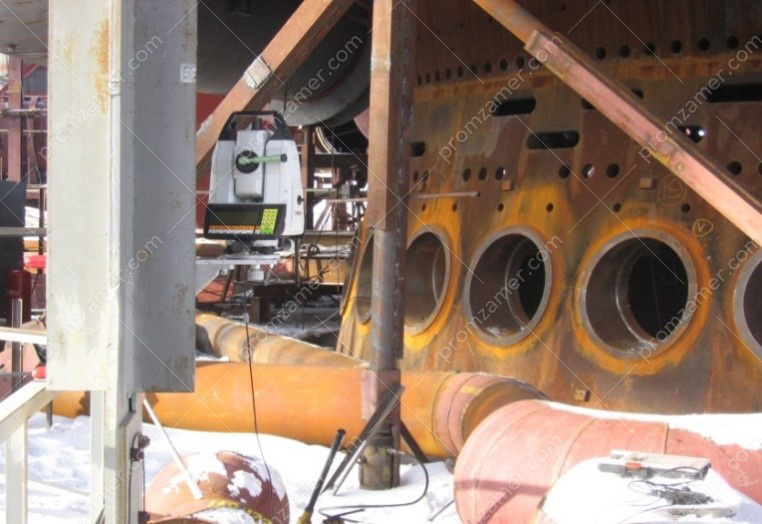
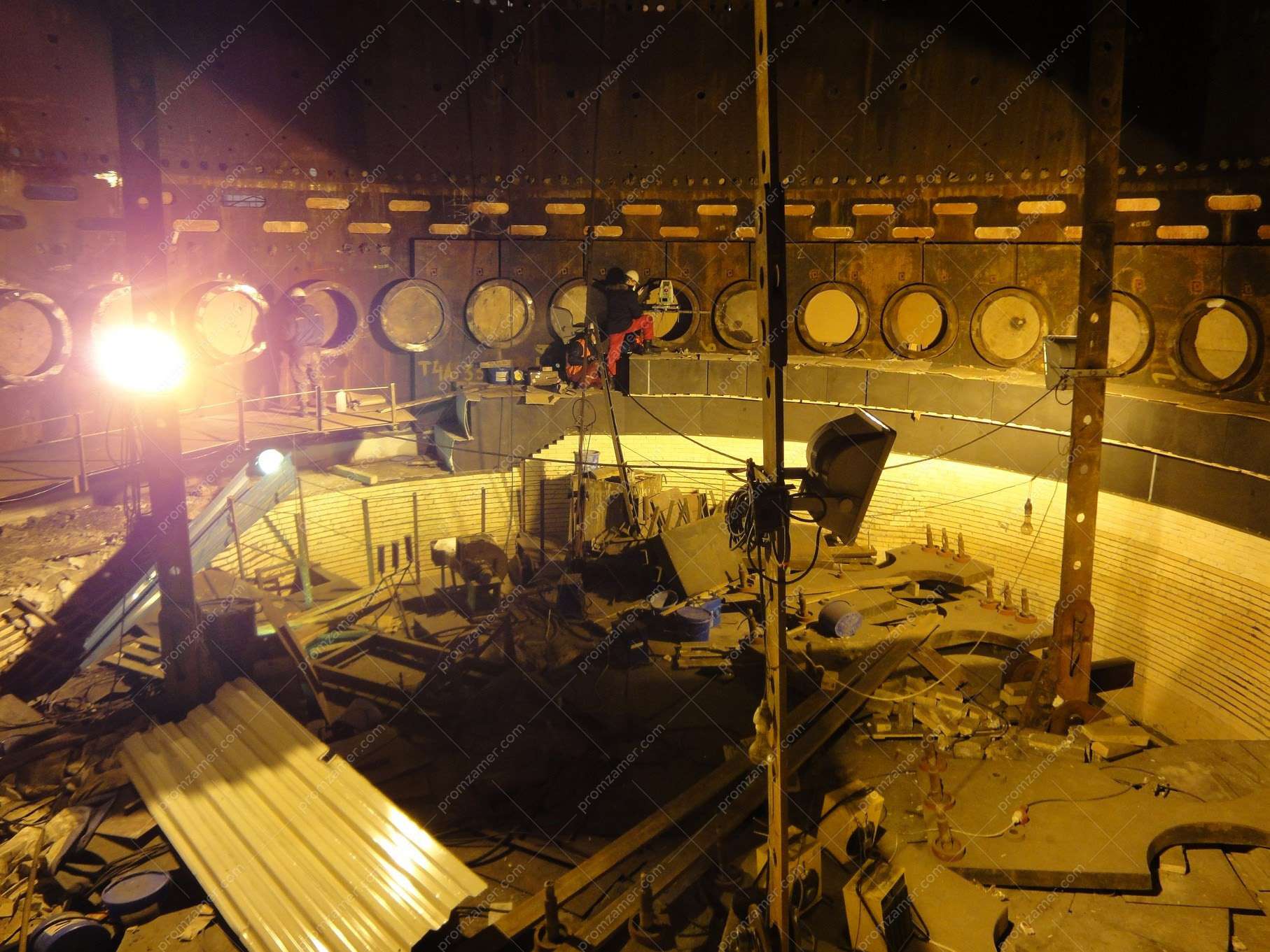
Positioning and aligning tuyere arches of the blast furnace
A blast furnace is one of the major components in the metallurgical industry and an integral link in the process of producing cast iron and ferroalloys from iron ore raw materials. Similar to all equipment in the ferrous metallurgy, the blast furnace must meet particularly high requirements for safety, reliability, faultless performance and durability. For this reason, special attention must be given to the stage of installation, alignment and adjustment of all components and parts of the blast furnace.
For instance, one of the furnace’s critical parts is the tuyere zone.
It is a steel cone with holes for installing tuyere connections through which high-temperature air is supplied in the process of iron smelting.
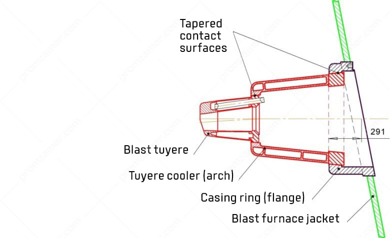
A tuyere connection of the blast furnace has three elements that are interconnected by means of tapered contact surfaces. The first element is a casing ring (“flange”) which is mounted in the furnace armor on a welded joint. It has a solid-cast uncooled structure.
The second element is the tuyere cooler (“arch”) which is inserted into the casing ring on a tapered joint. It is made of copper. It has a hollow cast structure and is water-cooled.
The third element is a blast tuyere. It has a hollow cast water-cooled structure with a welded steel flange. It is inserted into the arch by means of a tapered joint.

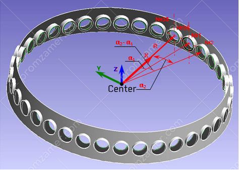
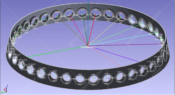
For stable, high-performance and economical operation, air must be supplied into the blast furnace evenly along the axes of air connections. The axes of the air connections must be evenly spaced around the perimeter in the same plane and intersect at one point on the vertical axis of the furnace.
To fulfill this condition, the casing rings must be carefully leveled when being installed in the blast furnace armor. The rings are fixed in the furnace armor using welded joints. Considering that during the fixing of the rings in the furnace armor, the design geometry of the axes changes due to stresses associated with welding, the axes of the casing rings must be subsequently adjusted.
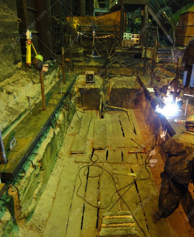
To achieve the design position of the casing rings after welding, the following operations are performed:
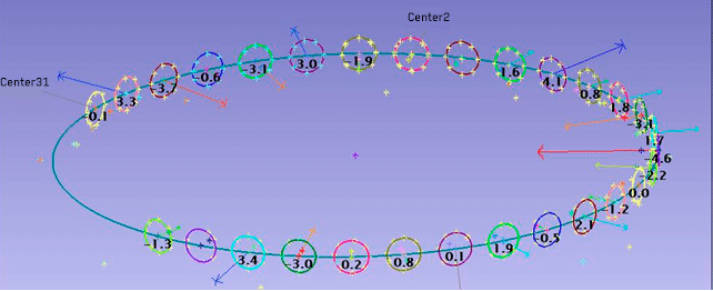
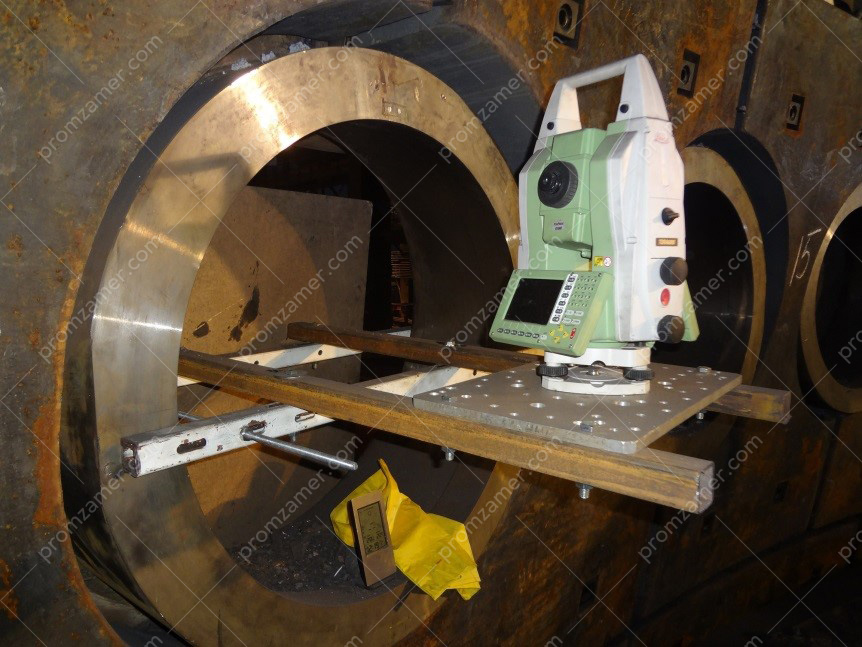
- Geodetic survey to inspect the actual position of the “flanges”, their axes and contact surfaces after welding them to the furnace armor.
- Adjustment of the position of the “flanges” and their contact surfaces by boring according to the following parameters:
- height;
- radial convergence on the furnace axis;
- tangential position (angle of circumference);
- If necessary, the contact surface is surface-welded before boring the “flanges”.
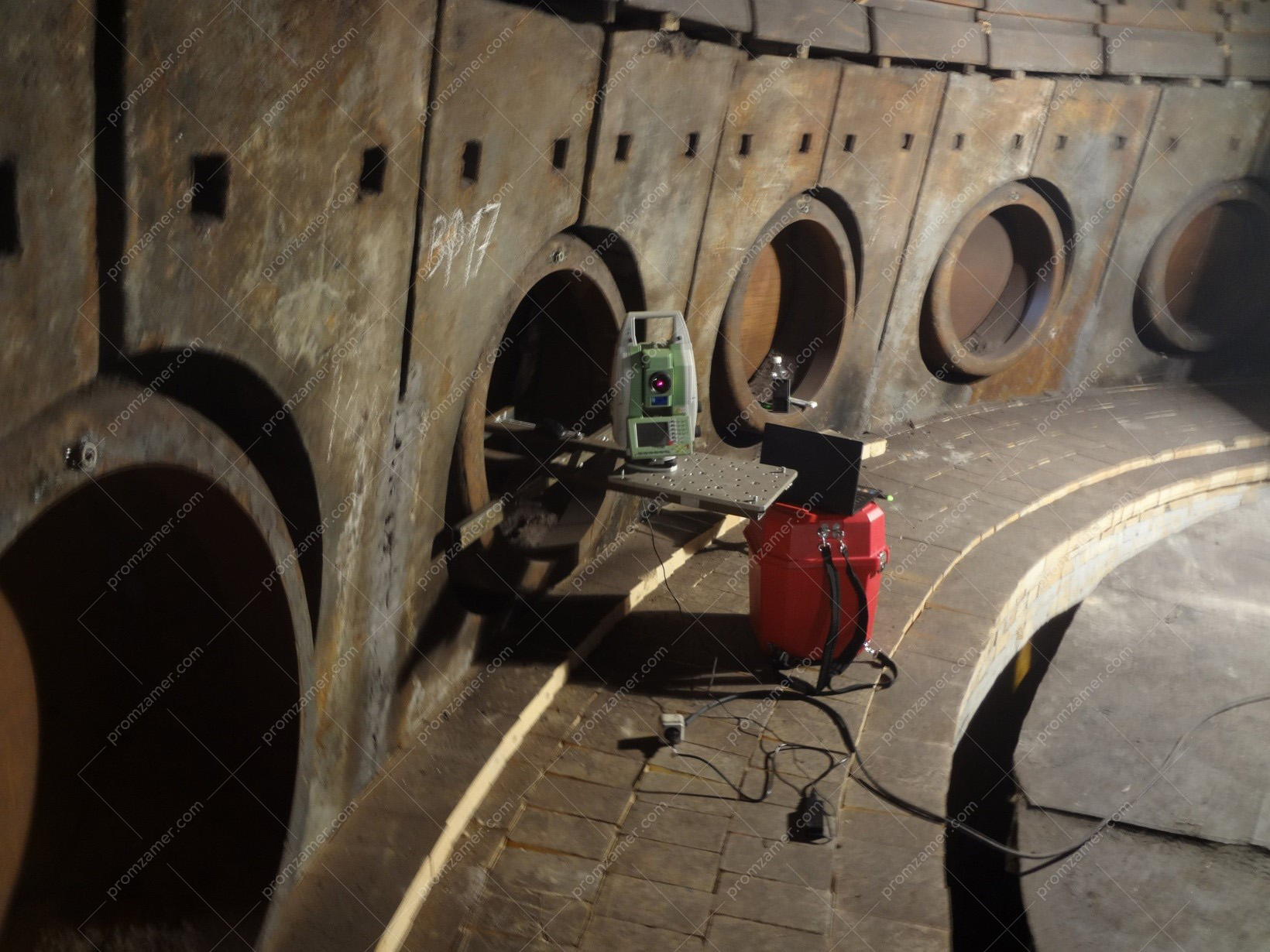
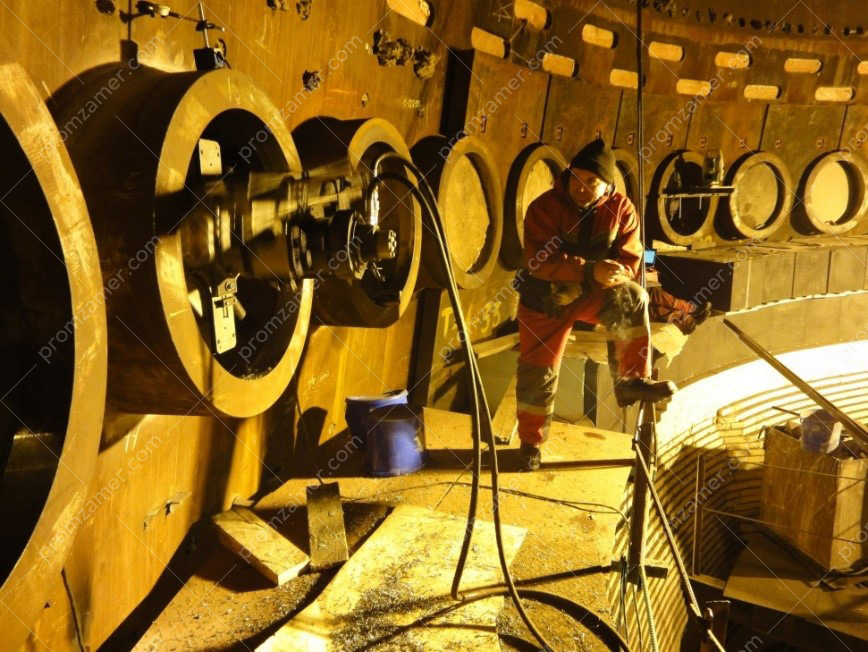
The main task our professionals faced was to accurately position the metal-cutting machine, which in turn machined the inner tapered surface of the welded flange.
Tell us about your project
We will contact you in 1 working day and prepare the info you need.
