

You are able to download printable version of this article in .pdf format for offline use!
Oil & Gas Sector
In our measurement activities, we only use state-of-the-art measurement systems and technologies.
Leica laser trackers AT403 offer the geometry measurement accuracy of 0.015 mm±0.006 mm/m. The error in determining the horizon level is 1ʺ (arc-second).
The ROMER Absolute Arm CMM provides accuracy of ±0.02 mm.
The oil and gas industry is of key importance for the global economy. For this reason, only modern technologies, equipment and materials are used in this sector. The highest effectiveness of equipment use is achieved in the construction of new facilities and upgrade of existing ones.
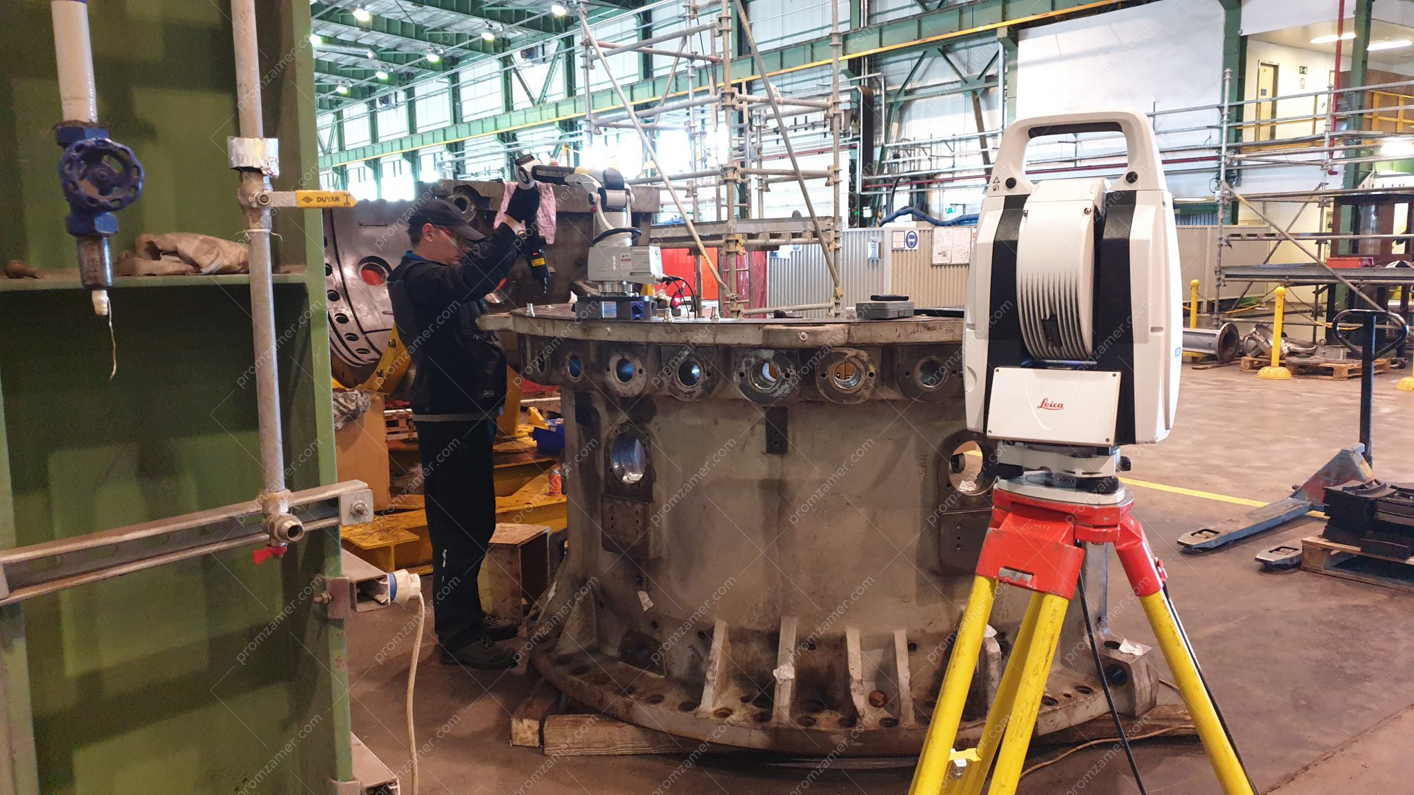
Measuring a turbine casing.
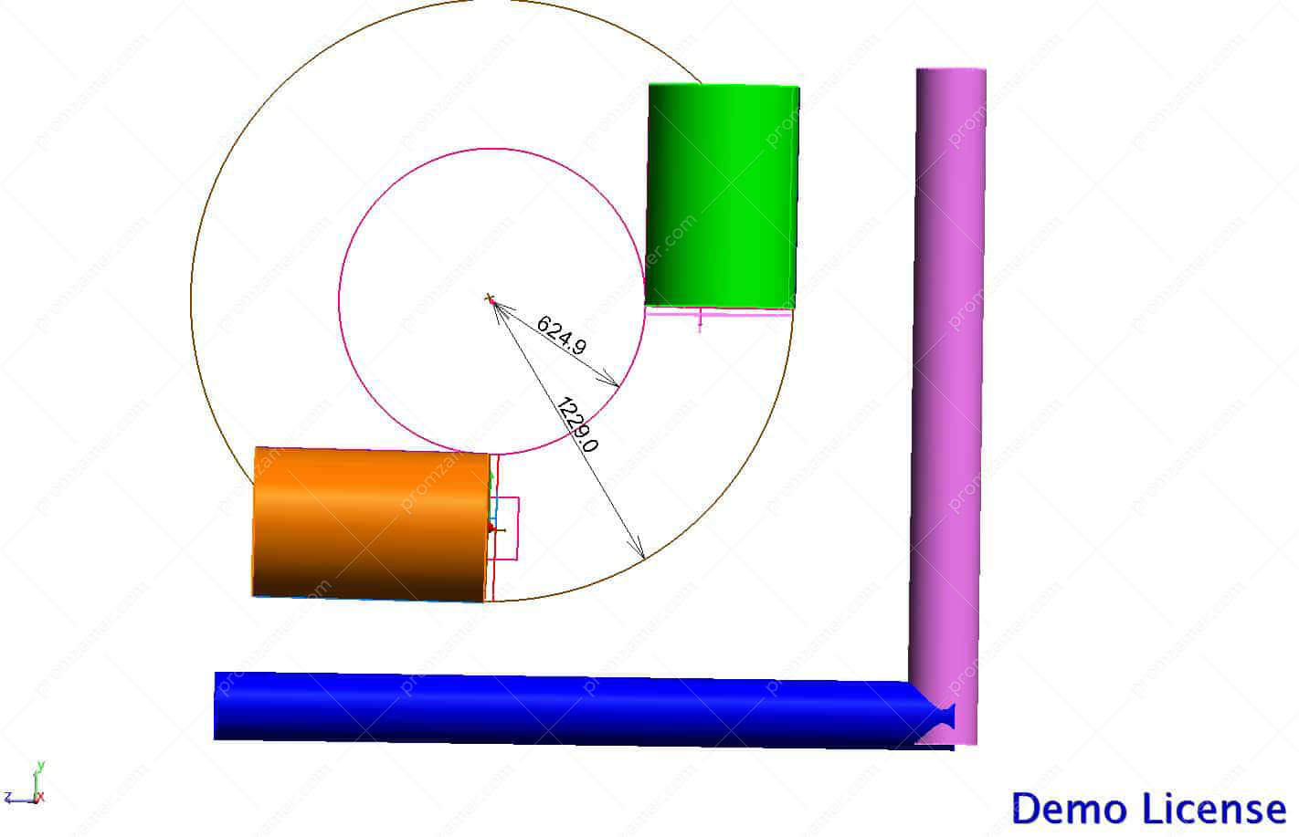
Determining the relative position of bends
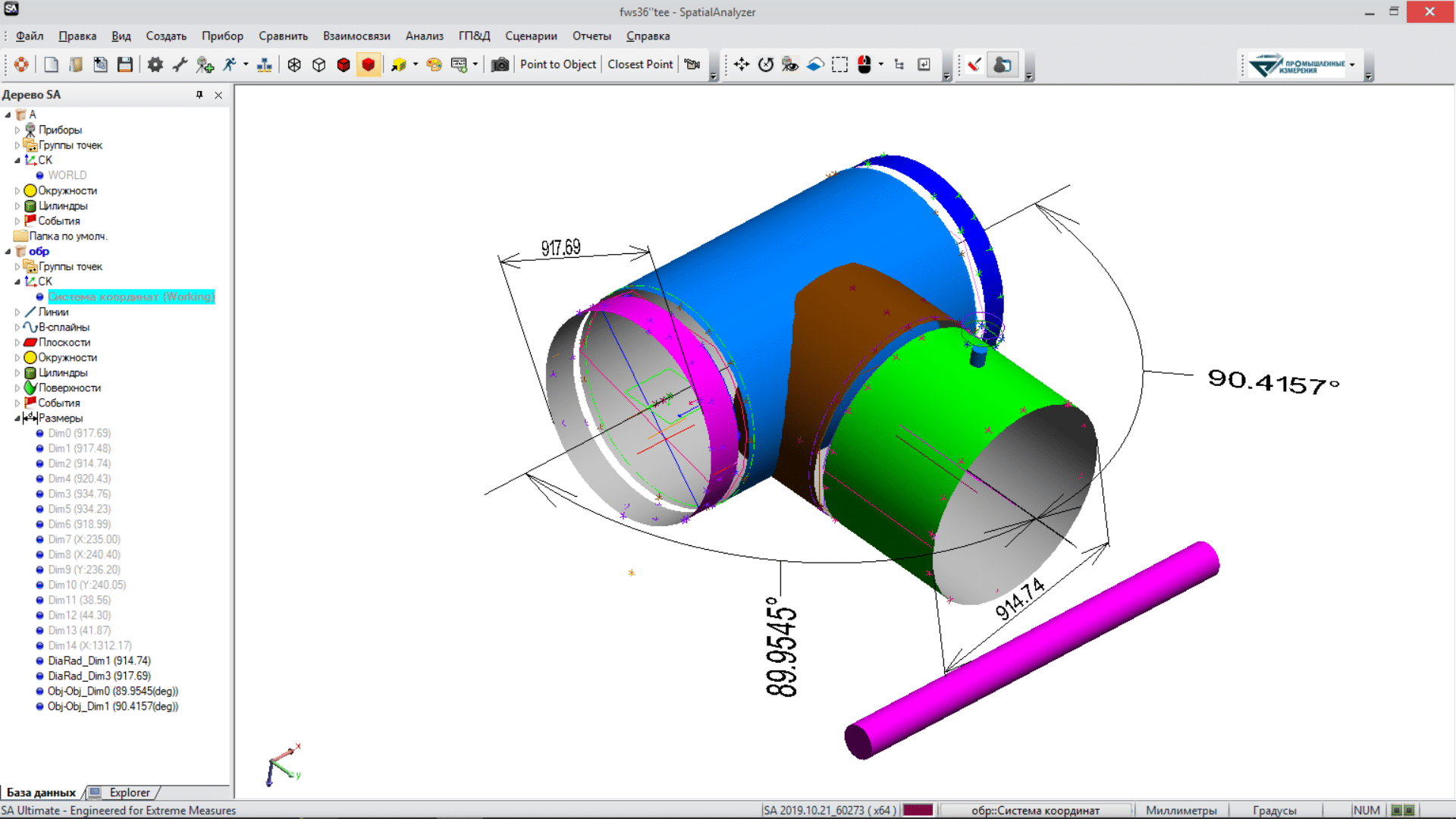
Relative position of a T-connection
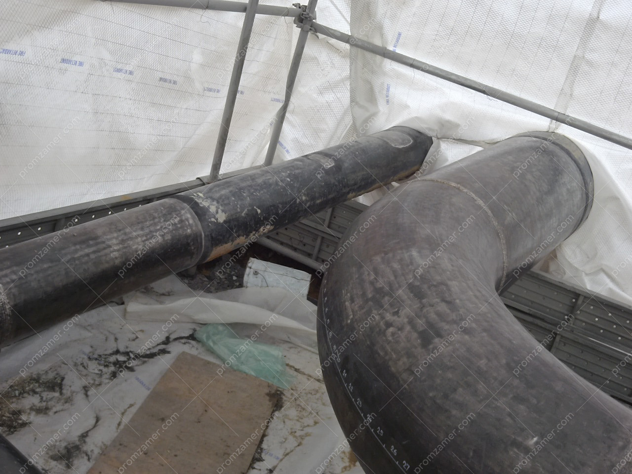
General view of a pipeline
Compared with traditional geometry inspection methods, the use of modern high-precision measuring instruments during on-site installation and quality control of manufacturing of major equipment in the oil and gas sector allows for not only ensuring conformity to the design position, but also for speeding up the installation process.
Types of activities during equipment geometry inspection:
Виды работ, выполняемые при контроле геометрии оборудования:
- Alignment of elements;
- Surface inspection for all surface shapes;
- Diameter determination;
- Determination of the radius relative to the geometric axis of the part;
- Concentricity of elements;
- Surface roughness;
- Inspection of the positional location of hole centers;
- Non-perpendicularity;
- Alignment of the centers of the control elements of the shaft;
- Other parameters at the customer’s request.
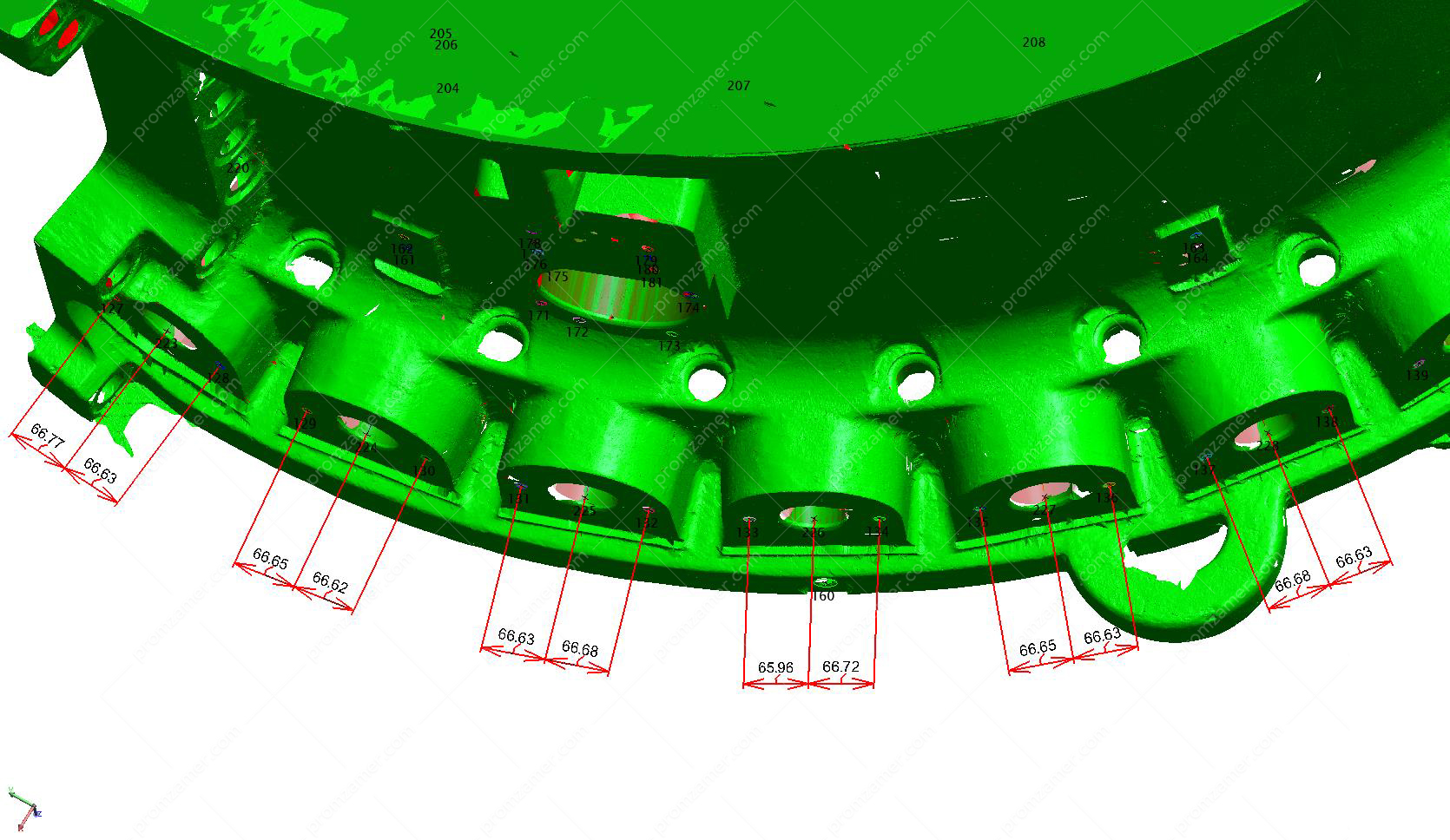
Determining the relative position of holes
Installation and marking support:

Determining the shape
Pipe cut marking on a section with an angle of 2º
- Marking for anchors with reference to an object’s axes;
- Marking of pipelines for lineup;
- Installation support when replacing a section of a pipeline;
- Alignment of drive shafts;
- Equipment assembly check;
- Installation support and adjustment of embedded plates for equipment installation;
- Relative positioning of major equipment;
- Horizontality, flatness of elements;
- Accuracy check during manufacture of large-sized parts, adjustment during manufacture.
Package of works when measuring a compressor:
- Inspection of compressor elements;
- Measurement of a casing’s geometry at the equipment installation site;
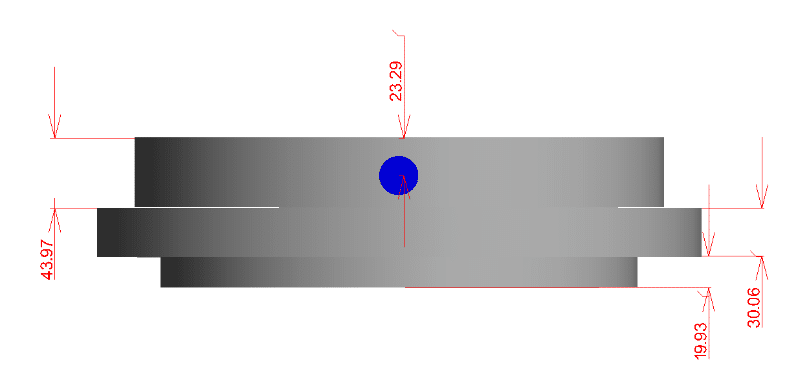
- Measurement of shaft dimensions and diameters at the place of installation of seals and bearings without dismantling the shaft from the compressor casing;
- Alignment of a shaft’s cylindrical surfaces;
- Other parameters at the customer’s request.
General view of a compressor
General view of the data obtained

Measuring a compressor’s sealing element
Creating an actual CAD model based on measurement data
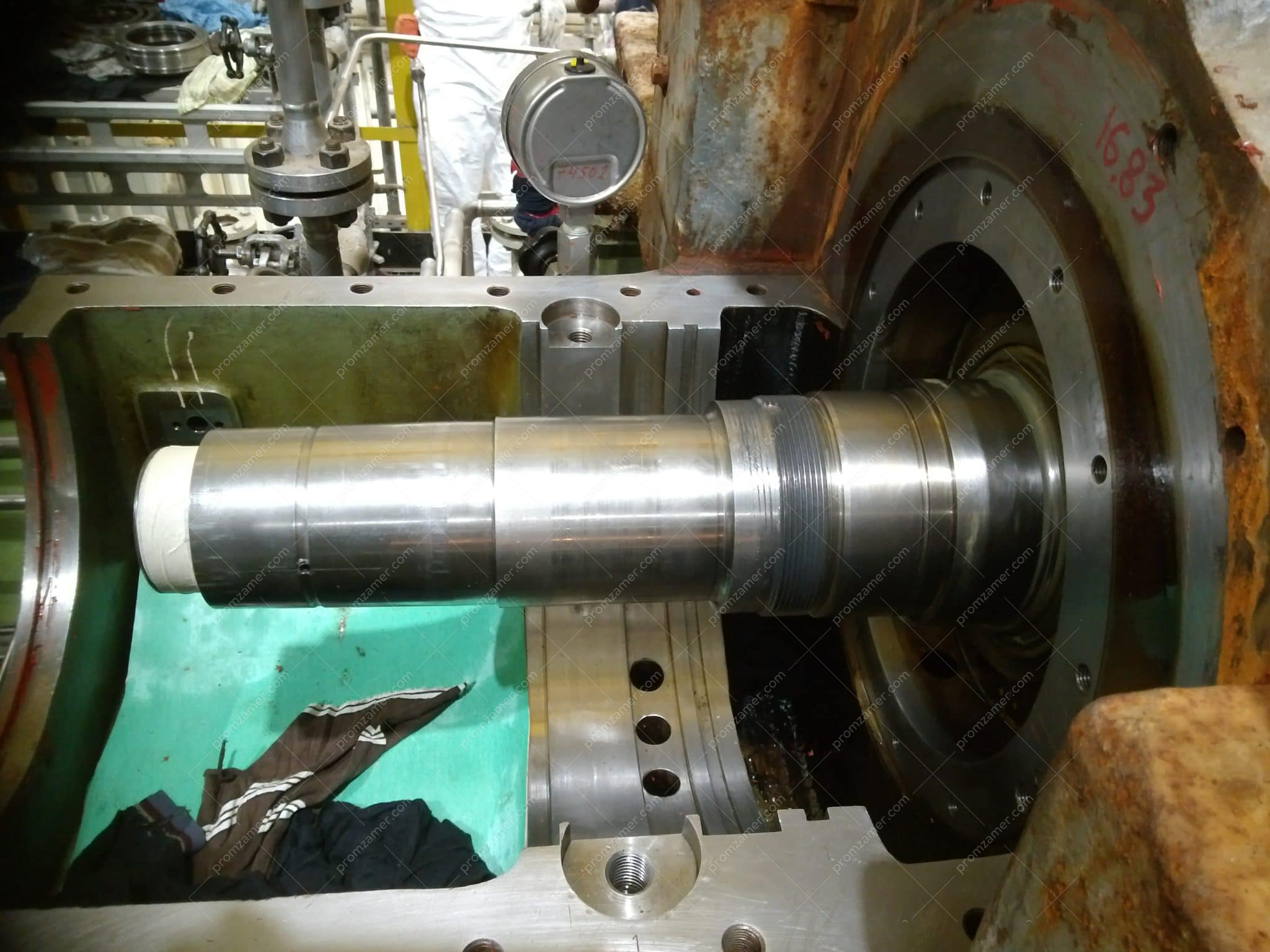
Measuring a compressor shaft at the equipment installation site
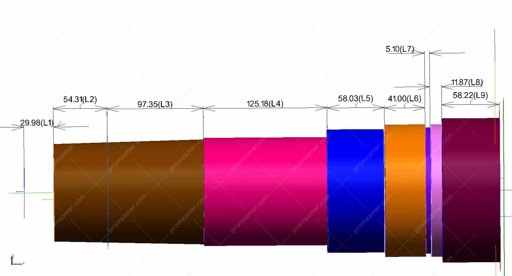
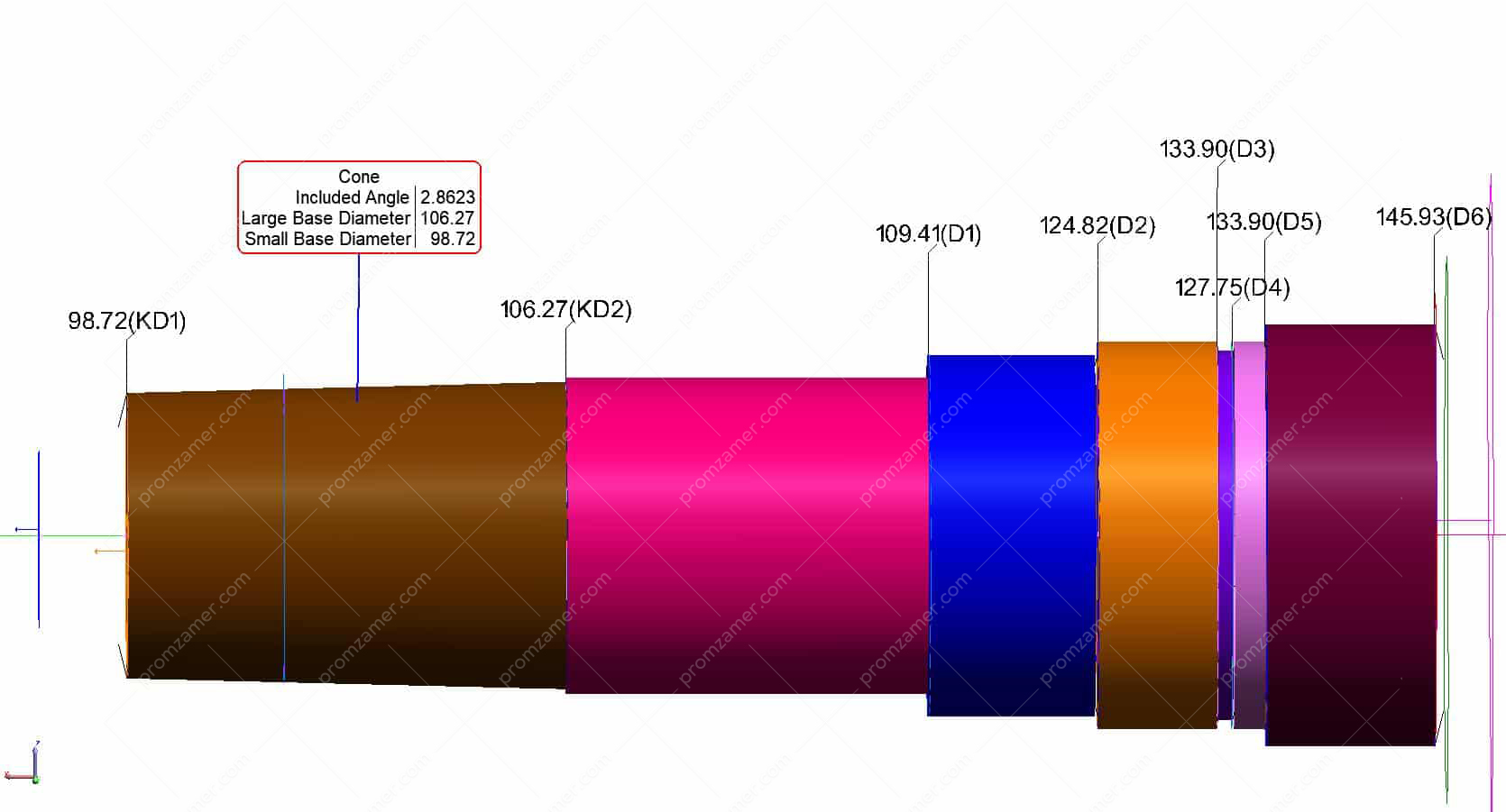
Result. We are able to create the most accurate CAD model using measurement data
Virtual assembly of objects. Reverse engineering
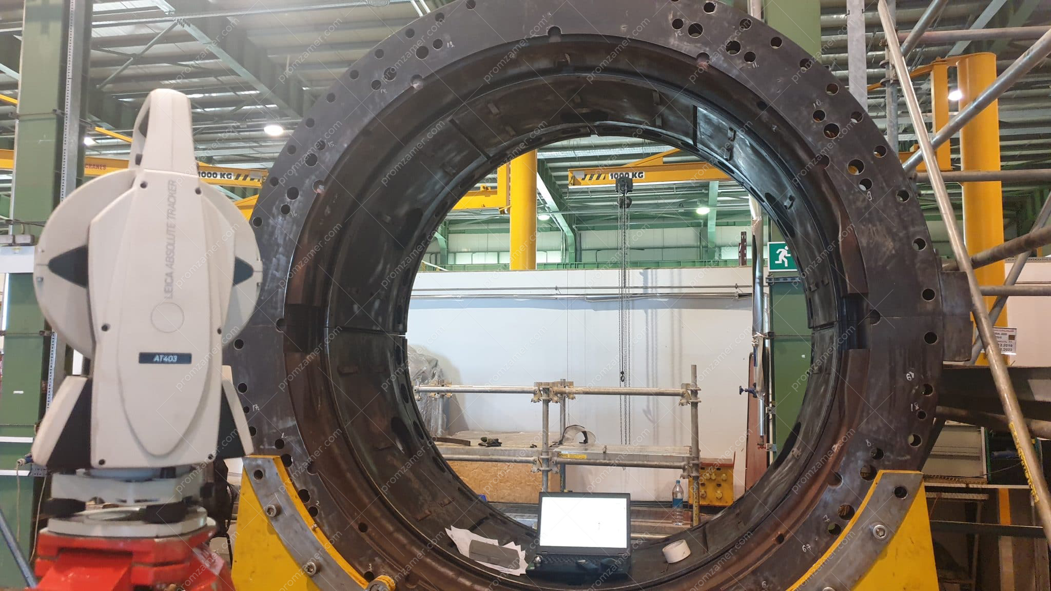
Measuring an assembled turbine casing
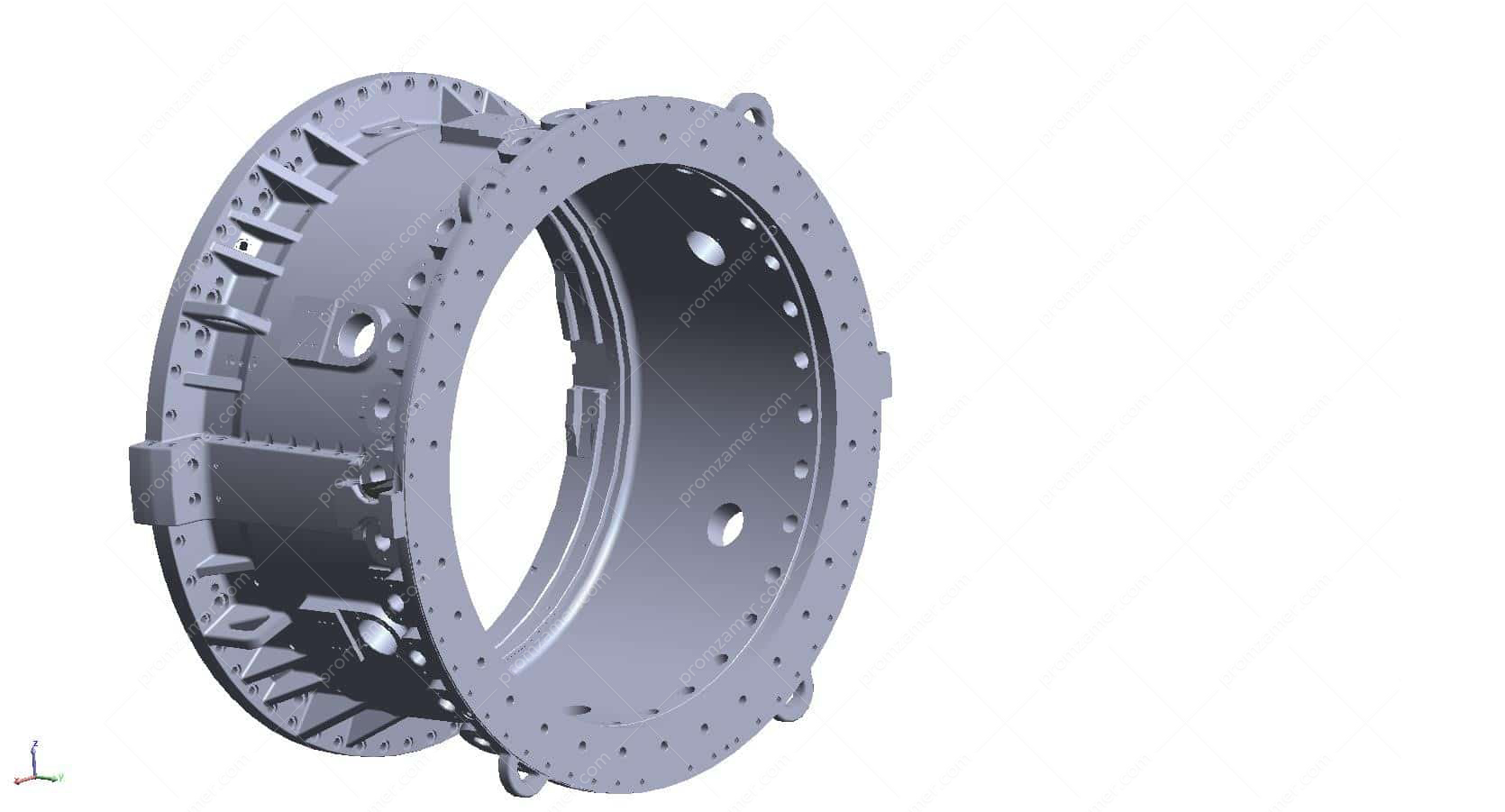
A solid model is built based on measurement and scanning results.
A solid model is built.
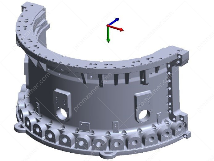
Actual geometry
Actual geometry
The use of virtual assembly and reverse engineering is justified when upgrading equipment, when existing parts are joined with newly manufactured parts.
The purpose of virtual assembly:
- inspection of newly manufactured parts and joining them with working parts
- fit-up, measurements of objects at different sites (at the manufacturer’s sites as well) that can be located at a great distance.
An example of high-precision measurement of the entire geometry of a turbine casing with subsequent high-precision scanning is given. As a result of the work, all actual dimensions of the casing were measured, a solid model was built to enable upgrading the turbine and manufacturing mating parts.
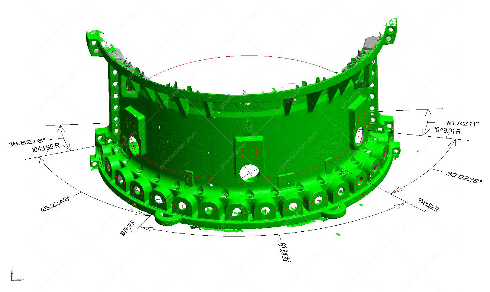
3D laser scanning
3D laser scanning is a technology that allows you to contactlessly determine the spatial coordinates of a large number of points on the surface of the measured object, the so-called point cloud. Our engineers’ experience and the equipment that we use allows for obtaining the most high-precision point clouds for objects with dimensions of up to 3 m with a spatial accuracy of 0.05 mm
Obtaining a point cloud for objects with dimensions of more than 3 m with an accuracy of 0.1 mm.
The customer receives both the point cloud proper and the results of its processing, i.e., built surfaces, solid models, assemblies. We can prepare drawings for the manufacture of a part based on scanning and measurement results.
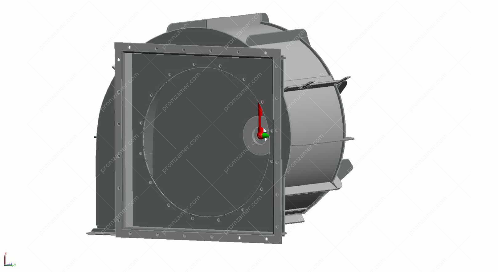
Below is an example of a scanned old casing of a supercharger and a runner; the purpose of the work is to develop a set of drawings for the manufacture of a new casing and a runner.
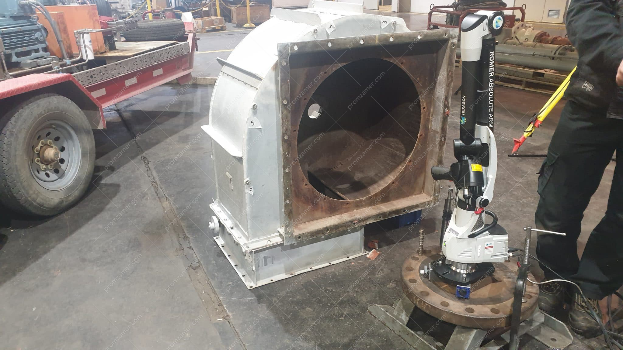
General view of a part
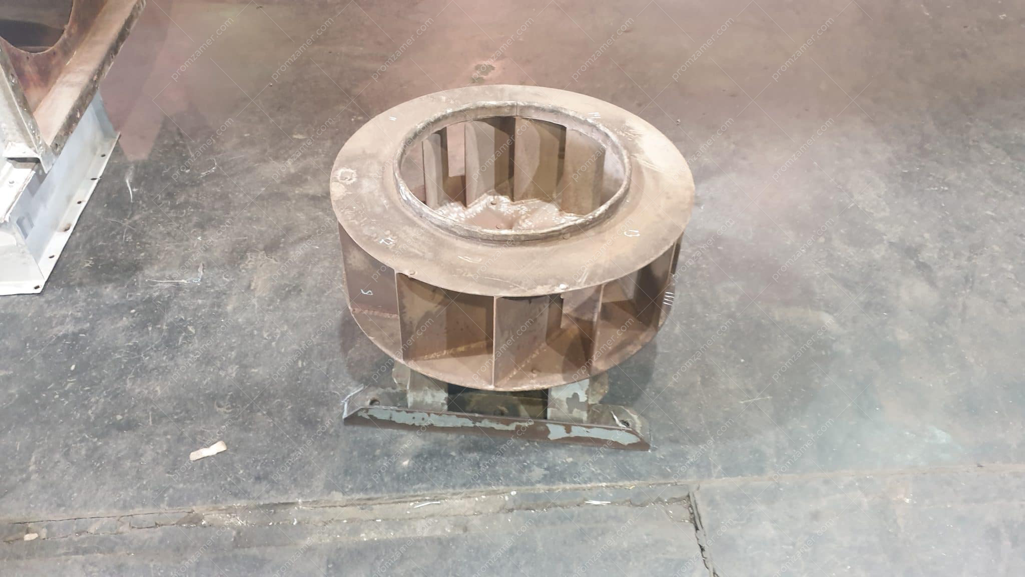
Runner
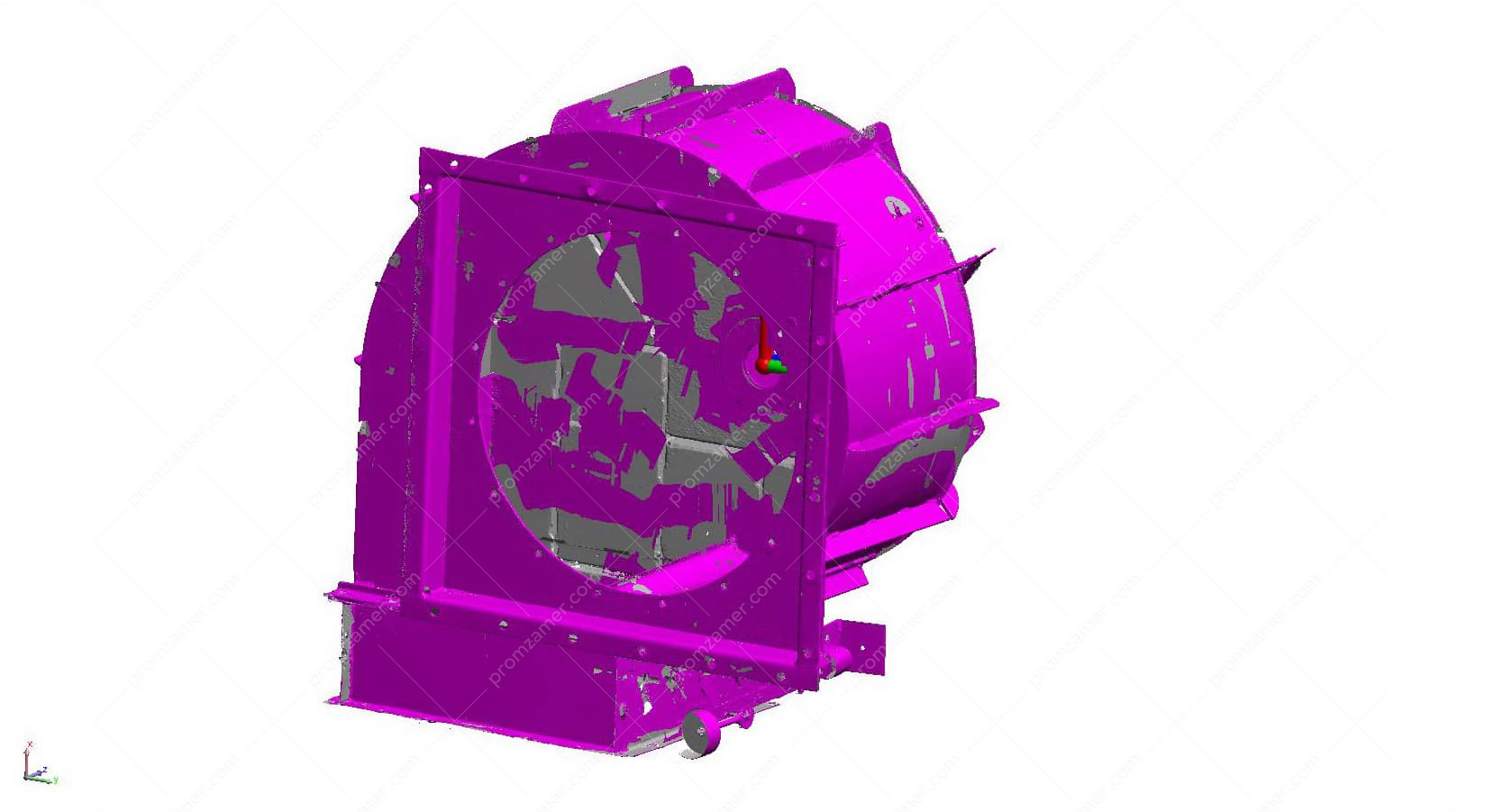
The resulting triangulation model of a part
A built CAD model.
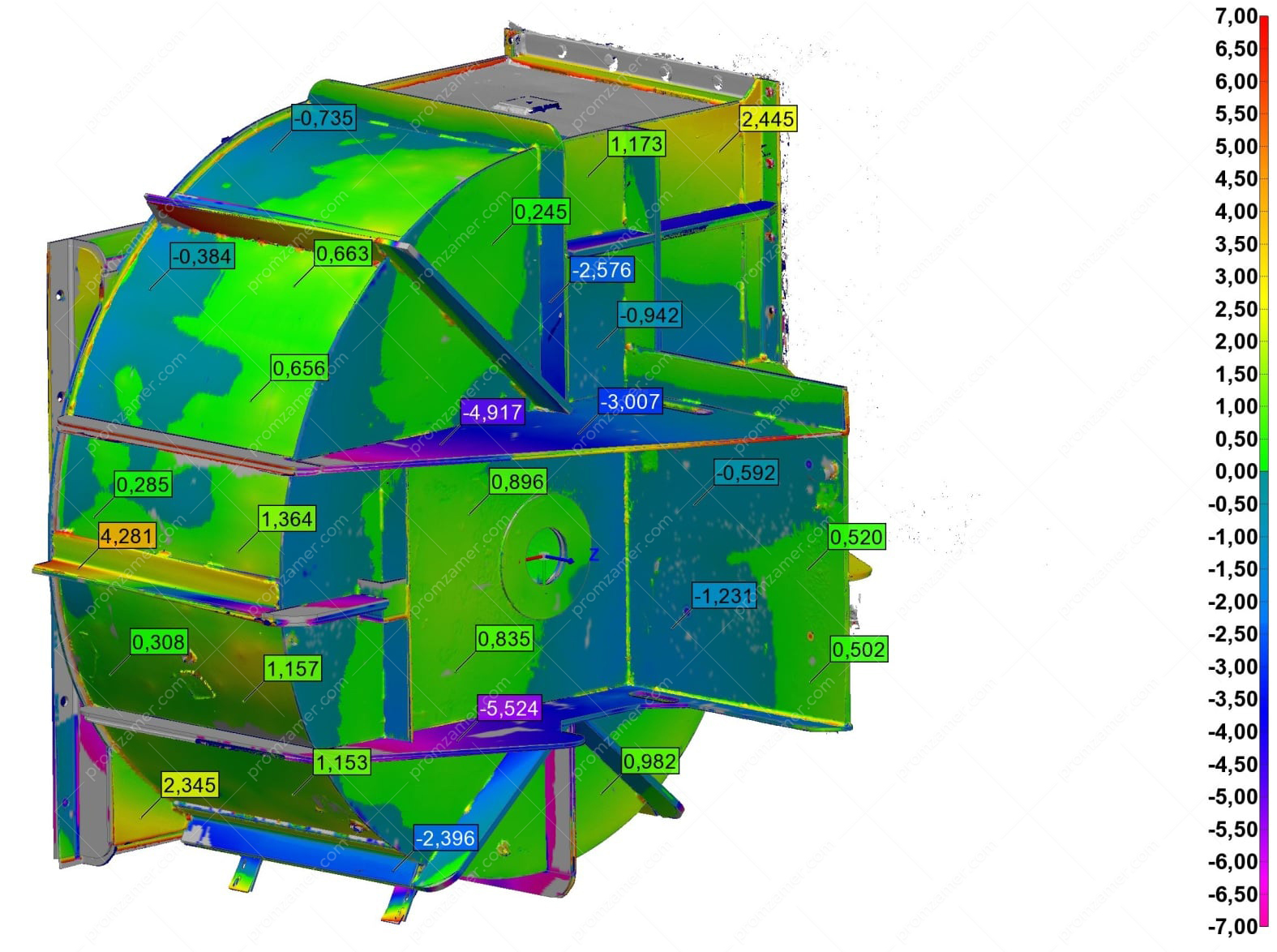
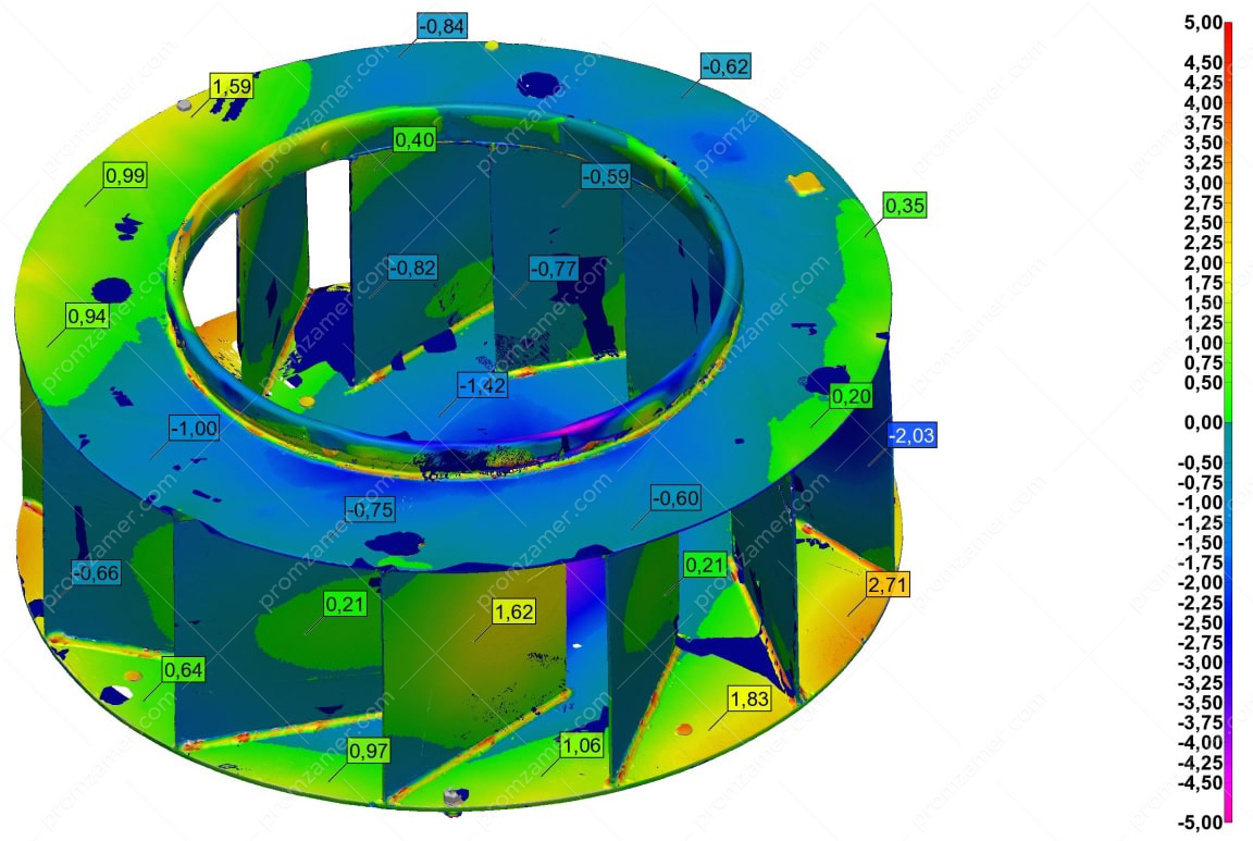
Comparison of the CAD model and the actual part
Tell us about your project
We will contact you in 1 working day and prepare the info you need.